
Subscribe to Our Youtube Channel
Related Manuals for Rion KS-16F

Summary of Contents for Rion KS-16F
- Page 1 INSTRUCTION MANUAL PARTICLE SENSOR KS-16F 3-20-41 Higashimotomachi, Kokubunji, Tokyo 185-8533, Japan...
- Page 3 Organization of this manual This manual describes the features and operation principles of the light- scattering type liquid-borne particle sensor KS-16F. In sections related to the configuration of a measurement system comprising the KS-16F and other equipment, this manual also touches upon operation of the other equipment, but to assure safe and correct operation, always consult the documentation of the other equipment as well.
- Page 4 Multi-point Monitoring System Explains the basics of setting up a multi-point monitoring system using the Rion multi-point interface. Specifications Lists the technical specifications of the unit. All company names and product names mentioned in this manual are trademarks or registered trademarks of their respective owners.
-
Page 5: For Safety
FOR SAFETY In this manual, important safety instructions are specially marked as shown below. To prevent the risk of death or injury to persons and severe damage to the unit or peripheral equipment, make sure that all instructions are fully understood and observed. - Page 6 WARNING Sample fluid danger prevention When toxic sample fluid comes into contact with any part of the human body or when toxic gases generated by the sample fluid are breathed, there is a danger of severe injury or death. When sample fluid comes into contact with other objects in the vicinity, there is a risk of fire, explosion, corrosion, deformation or other effects.
- Page 7 Before and after measurement, clean the entire sample fluid system thoroughly to remove any remnants. Otherwise unwanted effects such as thermal build-up, hardening, particle accumulation etc. can occur. This is especially important to prevent the possibility of serious accidents when using the unit to measure different types of sample fluids.
- Page 9 WARNING The unit uses a laser source This unit is designated as a class 1 laser product according to IEC 60825-1 (2001). The internal particle detector mechanism uses a laser, but it is fully shielded so that the beam cannot exit from the enclosure.
- Page 10 Warning Labels The following types of warning labels are used with this unit. Warning label for sample fluid and handling INLET and OUTLET The label specifies the maximum sample fluid pressure as 300 kPa (gauge pressure). The label is affixed to the front panel of the unit.
- Page 11 Laser product warning label (Class 3B) Indicates that the unit internally uses a laser classified as a class 3B laser product according to IEC 60825-1 (2001). The laser source can cause blindness if viewed directly, and can cause skin injuries if the skin is exposed directly to the beam.
- Page 13 Precautions Operate the unit only as described in this manual. Do not touch any parts of the unit other than necessary for operation. Before using the unit, make sure that all cable and PFA tube connections are correctly and safely established. In case of malfunction, do not attempt any repairs.
-
Page 14: Table Of Contents
Contents FOR SAFETY ................... iii Outline ....................1 Types of sample fluids ..............1 Laser source service life ............... 2 Transport ..................2 Particle size detection ..............3 Block diagram................3 Measurement system configuration example ....... 4 Controls and Features ................. 5 Main unit front panel .............. - Page 15 Maintenance ..................20 Steps after use ................20 Cleaning the piping ..............20 When the fuse has blown ............22 Serial Interface ................. 23 Transfer principle ................ 23 Serial connector ................24 Interface cables ................24 Message format................26 Command messages ..............29 Information request messages ............
-
Page 17: Outline
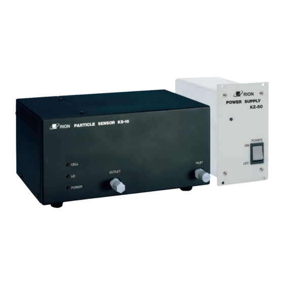
Outline The KS-16F is designed to be used as an in-line sensor in a system for measuring the size and number of particles in liquid, using the light-scattering method. Measurement results are output via a built-in interface. The KS-16F consists of the sensor unit and the power supply unit. -
Page 18: Laser Source Service Life
Outline Laser source service life The life expectancy of a laser diode such as used in the KS-16F is shorter than that of other semiconductors. When the laser diode nears the end of its service life, the light output falls below the rated level. There are considerable differences in service life between individual diodes. -
Page 19: Particle Size Detection
Outline Particle size detection The unit is calibrated at the factory, using particles of known diameter and refractive index (single polystyrene latex spheres with a refractive index of 1.6) in pure water. As the amount of scattered light by such particles is used as reference to determine the particle size, the measured size corresponds to the light-scattering size of polystyrene latex particles. -
Page 20: Measurement System Configuration Example
For details on how to perform measurement control and how to read measurement results etc., please refer to the section "Serial Interface" on page 23. It is also possible to configure a multi-point monitoring system using the Rion multi-point interface. For details, please refer to the section "Multi-point Monitoring System"... -
Page 21: Controls And Features
Controls and Features Main unit front panel CELL indicator Lit (green) : Particle sensor (flow cell) is operating normally. Lit (red) : Particle sensor is not operating normally, due to contamination, condensation or other causes, or particle concentration in sample fluid exceeds maximum rating of unit. -
Page 22: Main Unit Rear Panel
Controls and Features Main unit rear panel ALARM 1 terminal, ALARM 2 terminal These terminals serve for output of an alarm signal. Under control from external equipment via the DATA LINK (multi-point interface), the terminals can be opened or closed. The two alarm circuits can be used independently. - Page 23 Controls and Features POWER switch Serves to turn the unit ON and OFF. PURGE inlet Purge gas for cleaning the unit (to prevent degradation of the optical and electrical systems) is to be supplied via this inlet. For details, please refer to the section "Purge gas"...
-
Page 24: Power Supply Unit Front Panel
Controls and Features Power supply unit front panel Power indicator Lights up when the unit is powered. POWER switch Serves to turn the unit ON and OFF. -
Page 25: Power Supply Unit Rear Panel
Controls and Features Power supply unit rear panel DC OUT connector Output for powering the KS-16F. Use the supplied DC cable to link this connector with the DC IN connector on the KS-16F. AC LINE connector Serves for connection to an AC outlet (90 to 250 V, 50/60 Hz). -
Page 26: Preparations
OFF before making any connections. 2. Use the supplied DC cable to link the DC IN connector on the KS-16F with the DC OUT connector on the KZ-50. 3. Plug one end of the power cord into the AC LINE connector on the KZ-50 and plug the other end into a grounded AC outlet. -
Page 27: Connecting The Sampling Tubes
Preparations Connecting the sampling tubes 1. Remove the end plugs from the INLET and OUTLET connectors of the KS-16F by turning the plugs counterclockwise. Important Store the end plugs in a safe place, since they will be needed when the unit is sent to the supplier for servicing and maintenance. -
Page 28: Removing The Sampling Tubes
Preparations 3. Slide the tip of the sampling tube onto the INLET connector and turn the nut clockwise to fasten the tube. Connect the OUTLET side in the same way. Removing the sampling tubes 1. Purge the unit with pure water to remove any sample fluid remnants. If the use of pure water poses the risk of sample fluid reaction and thermal build-up, hardening, or particle accumulation, use a different cleaning agent that is suitable for the sample fluid, and finally purge with clean... - Page 29 Preparations 3. Place the end plugs on the INLET and OUTLET connectors and secure the plugs by turning them clockwise (see above illustration). 4. Insert the plug of the sampling tube into the flared section at the tip of the sampling tube and turn the nut clockwise to secure it. Important The flared section will contract slightly over time.
-
Page 30: Purge Gas
Preparations Purge gas In the cases listed below, the interior of the unit should be cleaned with purge gas supplied to the PURGE inlet, to prevent problems such as moisture condensation or adverse effects on the electrical circuitry. If the temperature of the sample fluid is lower than the ambient temperature, so that moisture condensation may occur in the particle detector. -
Page 31: Before Supplying The Sample Fluid
Observe the pressure limits for the sample fluid system. The cell and INLET and OUTLET of the KS-16F are made of synthetic quartz and PFA. Never use sample fluids such as hydrofluoric acid which can cause corrosion of fluid-contacting parts. Otherwise leaks or seepage may occur. -
Page 32: Transfer Rate/Node Address Setting
Preparations Transfer rate/node address setting Before turning the unit on, set the transfer rate and the node address as described below. The switch bank for these settings is located on the rear panel. Note The setting of the transfer rate/node address setting switch bank is read only when the unit is turned on. -
Page 33: Turning The System On
Preparations Turning the system on Important Before turning the system on, make sure that the internal piping is completely filled with sample fluid. If the interior of the cell is dry, the laser beam may burn contamination into the cell lining, causing an increase in noise. -
Page 34: Measurement
For details, please refer to the documentation of the external equipment. Measurement procedure The KS-16F can perform a single measurement under control of commands (measurement start/stop/cancel) sent from a computer or similar equipment. This is called the manual measurement mode. - Page 35 Measurement Stopping the measurement The measurement can be prematurely stopped in one of the following ways. Measurement cancel command is received ("G2" via serial interface) Initialization command is received ("C" via serial interface) Light source off command is received ("L0" via serial interface) Cover is opened If the measurement is canceled in one of the above ways, no measurement result data will be available (measurement result message is not sent).
-
Page 36: Maintenance
Maintenance Steps after use When removing the KS-16F from the measurement system, observe the following points. 1. Clean the piping with pure water. For more information, please refer to the section "System configuration example for cleaning" on page 2. Set the POWER switch to OFF and disconnect the power cord from the AC outlet. - Page 37 Maintenance 3. Cleaning with cleaning fluid Use pressurization or suction within the prescribed range to pass cleaning fluid through the system. Flow rate control is not necessary. After an ample amount of cleaning fluid has been passed through the system, check the CELL indicator. Suitable cleaning fluid : Optical cleaning fluid, acetone, alcohol or similar Required equipment...
-
Page 38: When The Fuse Has Blown
The fuse is contained in the FUSE holder on the rear panel. Open the holder by turning it counterclockwise and remove the fuse. Caution Before replacing the fuse, turn off the power at the KS-16F and the power supply unit KZ-50 and disconnect the DC cable that links the KS-16F to the KZ-50. Important Replace the fuse only with the supplied spare fuse. -
Page 39: Serial Interface
Except for the transfer rate, the parameters at the KS-16F side are fixed, therefore the external equipment must be adapted to these parameters. For information on how to change the transfer rate of the KS-16F, please refer to the section "Transfer rate/node address setting"... -
Page 40: Serial Connector
Must be kept on Open * Input/output assignments as seen from KS-16F. Interface cables Two types of optional cables are available from Rion for interfacing to external equipment (cable length 2 m). Choose the cable that fits the requirements of the equipment. CC-61... - Page 41 Serial Interface...
-
Page 42: Message Format
"D", <CR>, <LF>. Note In this manual, the message terminator is expressed as <EOL>. Messages sent from external equipment to the KS-16F are of the following two types: Command message: Serves to control a function of the KS-16F. Information request message: Serves to request information (data) from the KS-16F. - Page 43 Serial Interface Message header All messages are preceded by a header which consists of a capital letter and a forward slash, such as "J/" in the message "J/G0E0M2". Since the message header denotes the type of message, it can be used to determine what kind of message has been received.
- Page 44 When the KS-16F has received an information request message, it outputs the corresponding information message. If it has received a command message or if there was an error in the received message, the KS-16F outputs a response message. Automatic send of measurement data...
-
Page 45: Command Messages
Serial Interface Command messages External equipment can control operation of the KS-16F by sending appropriate command messages. A command message starts with the header "X/" followed by one or several commands. Examples: X/C<EOL> X/L1S1<EOL> When the KS-16F receives a command message, it returns an appropriate response message. - Page 46 Serial Interface Command list Command Function Remarks Reset KS-16F Single Set local mode/remote mode Activate local mode Activate remote mode Set measurement data send mode Activate S0 mode (data sent after measurement) Activate S1 mode (data sent after B command)
- Page 47 Example: X/C<EOL> Note If the "C" command is input while the KS-16F is send- ing a message to external equipment, the remaining part of the message is discarded, i.e. the received mes- sage will be truncated. Sending the "C" command...
- Page 48 This command is only accepted when the KS-16F is in remote mode. If "L0" or "L1" is sent while the KS-16F is in local mode, the response message "R/ ER3" is returned and the command is disregarded. When the "C" command is used, the light source is lit and the effect of the "L0"...
- Page 49 Serial Interface Set remote mode/local mode Command "Rn" R0 Activate local mode. In local mode, light source on/off cannot be controlled. R1 Activate remote mode. In remote mode, light source on/off can be controlled. The default at power-on is the local mode. Example: X/R1<EOL>...
- Page 50 This is called "S0 mode". S1 Measurement data are only output when a information request message ("Q/D") is sent from the external equipment to the KS-16F. This is called "S1 mode". The default at power-on is the S0 mode. Example:...
-
Page 51: Information Request Messages
Information request messages By issuing a information request message, external equipment can request information from the KS-16F. When the KS-16F receives such a message, it outputs the corresponding information message. A information request message starts with the header "Q/" followed by a single character that indicates the kind of requested information. -
Page 52: Information Messages
Serial Interface Information messages Information messages serve to indicate the status of the KS-16F and to transfer measurement data to external equipment. The following information messages are used: Function status information message Current status information message Current error information message... - Page 53 Serial Interface Function status information message The function status information message indicates various measurement parameter settings of the KS-16F. The message is output in response to the function status information request message "Q/F". The format of the message is as follows: F/VnDnHnLnSn<EOL>...
- Page 54 Serial Interface Current status information message The current status information message indicates the current operation status of the KS-16F. The message is output in response to the current status information request message "Q/J". The format of the message is as follows: J/GnEnMn<EOL>...
- Page 55 Serial Interface Current error information message The current error information message indicates information on the current error status of the KS-16F. The message is output in response to the current error information request message "Q/K". The following messages are used.
- Page 56 S1 mode Measurement data are sent to the external equipment when the KS-16F receives the measurement data request information message "Q/D". The data for one measurement can be sent only once. If there is a measurement data request while no measurement data are available, only "D/<EOL>"...
- Page 57 Serial Interface Examples If measurement was carried out normally: D/KS-16F[10ML],000276919,000019176,000002561,000000396,000000008<EOL> If the particle count has exceeded 8 digits (over-range): D/KS-16F[10ML],100006847,000019176,000002561,000000396,000000008<EOL> If an error has occurred during measurement: D/KS-16F[10ML],200276916,200019176,200002561,200000396,200000008<EOL> Note Check the contents of the error with the measurement error information message.
- Page 58 Serial Interface Measurement error information message The measurement error information message indicates information on the error status of the immediately preceding measurement. The message is output in response to the measurement error information request message "Q/E". The following messages are used. (Listed in order of priority) E/TEMP_NG<EOL>...
- Page 59 The message is output in response to the particle size information request message "Q/S". The message has the following format. S/0.1UM,0.15UM,0.2UM,0.3UM,0.5UM<EOL> UM: Particle size unit (µm) Note The particle size ranges of the KS-16F are ≥0.1 µm, ≥0.15 µm, ≥0.2 µm, ≥0.3 µm, ≥0.5 µm.
-
Page 60: Response Message
Light source control was attempted in local mode. If a command message with more than one command is sent, the KS-16F waits until the last command is received, and then returns one response message only. If there is an error anywhere in the command message, the response message will be an error message. -
Page 61: Multi-Point Monitoring System
Multi-point Monitoring System The KS-16F incorporates the proprietary Rion multi-point system interface which allows connection to a multi-point monitoring system. For actual examples of multi-point monitoring systems. For details, please consult your supplier. The general configuration of a multi-point monitoring system is shown below. -
Page 62: Specifications
Specifications Optical system 90º sideway light-scattering method Light source Laser diode (rated output 200 mW; wavelength 830 nm) Laser product classification Class 1, IEC 60825-1 (2001) Internal particle detection mechanism uses Class 3B laser Light detector PIN type photodiodes Materials of component parts exposed to sample fluid sapphire, PFA Allowable sample fluid types Fluids which do not corrode the fluid contact materials... - Page 63 Specifications Allowable sample fluid pressure 300 kPa or less (gauge reading) Warm-up time 10 minutes Sample fluid connectors INLET : Sample fluid inlet, 2×4 dia. flared tube joint OUTLET : Sample fluid outlet, 2×4 dia. flared tube joint PURGE : Purge gas inlet, Rc 1 / 8 (1 / 8 PT female) Indicators CELL...
- Page 64 -10 to +50°C, less than 85% RH (no condensation and no freezing in internal piping) Dimensions and Weight Main unit (KS-16F): 248 (W) × 124 (H) × 193 (D) mm (Max. ) 240 (W) × 110 (H) × 150 (D) mm (excluding protrud- ing parts) Approx.
- Page 65 Specifications Main unit (KS-16F) dimensions Unit: mm...
- Page 66 Specifications Power supply unit (KZ-50) dimensions Unit: mm...
- Page 68 No. 25971 04-08 Printed in Japan...
Need help?
Do you have a question about the KS-16F and is the answer not in the manual?
Questions and answers