
Related Manuals for Tsuruga 8528

Summary of Contents for Tsuruga 8528
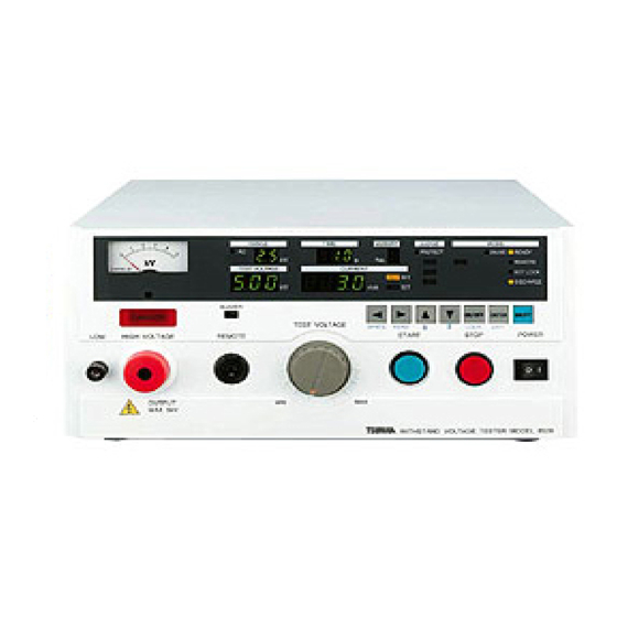
- Page 1 MODEL 8528 Withstanding Voltage Tester Instruction Manual TSURUGA ELECTRIC CORPORATION I-01882-1...
- Page 3 [Explosive material], [Flammable material], [Inflammable material], [Flammable gas], [Oxidizing material] ※Model 8528 internally uses the metallic materials. There is a fear of deterioration due to corrosion or rust and explosion or inflaming by an electric spark. Do not put anything on the 8528 or use it as foot stool.
- Page 4 Do not carry the product holding its red bushing at high voltage output terminal section (refer to ⑥,⑲ of the article 3 Name of parts and functions). ※The bushing (red) may break, causing serious injury by the fallen 8528. Minimize the mechanical shock or vibration when transporting the product.
-
Page 5: Table Of Contents
Contents Page Page 1. Preface ..............1 9. Test procedure (from start to judgement result) 22 1.1●Initial setting at the time of delivery ..1 9.1●Setting of test voltage (before starting test) 2. Confirmation prior to use ........2 ..............22 2.1●Unpacking.......... -
Page 7: Preface
Please make sure that this instruction manual reaches the responsible person of operation and also keep it near the tester so the operator can read it any time. Model 8528 deals high voltage, so it is designed to provide many protective functions and various concerns to secure the operators’ safety. -
Page 8: Confirmation Prior To Use
● Cautions for handling Since the Model 8528 deals high voltage, it is designed paying special attention to safety. However, it is still dangerous as it outputs high voltage of max. 5kV. An erroneous handling may cause fatal accident. In order avoid any accident, please strictly observe the following cautions and take utmost care for safety. -
Page 9: Name Of Parts And Functions
HIGH VOLTAGE REMOTE START STOP POWER OUTPUT MAX 5kV WITHSTAND VOLTAGE TESTER MODEL 8528 ① Power supply switch. Press right to turn ON and left to turn OFF. POWER ② Switch to interrupt the test operation, to reset a judgement. STOP ③... - Page 10 Name of parts and functions ⑪ Buzzer hole Aperture for the buzzer. WARNING Do not put any thing in the buzzer hole or insert a screwdriver or else. It may cause electric shock if touched with metal piece. ● It may also cause trouble of breakdown or mal-function. ●...
- Page 11 Name of parts and functions Memory No. display Displays memory number being set in the memory mode. MEMORY No. lamp Lit up when the PROTECTION is output. PROTECT ON/OFF ENTER SHIFT WRITE READ LOCK EXIT ⑬ Setting keys Keys to set the test condition such as referential voltage, leak current, test time etc.
-
Page 12: Rear Panel
Name of parts and functions ● Rear panel RS-232C HIGH VOLTAGE FUSE 7A 100V 50/60Hz REMOTE/OUT OUTPUT MAX 5kV STATUS OUT REMOTE 注 意 c START STOP REAR:ON VOLTAGE MONITOR CAUT ION NC + - 保 護接 地 端子 は確 実に 大... - Page 13 Name of parts and functions Terminal blocks for remote control. REMOTE When the terminal is in short-circuit, the test is started by START C REAR:ON C short-circuiting the terminal. START C connector ⑤ is in use, When the terminal is REMOTE START C disabled.
-
Page 14: Preparation Prior To Use
4. Preparation prior to use ● Zero adjustment of output voltmeter Before powering ON the power source switch, please confirm that the pointer of the output voltmeter ⑧ indicates “0”. If it is deviated, make an adjustment turning the zero adjuster ⑨ with the screwdriver. ●... -
Page 15: Connection Of Power Supply Cable
After connecting the low voltage side cable to the terminal, make sure to fix the locking metal to the terminal. LOW terminal ⑦ or ⑳ LOW voltage side cable(black) 8528 Main Locking metal Fasten the U-shape ditch side to the LOW terminal of the tester main unit. WARNING If the low voltage side cable is disconnected, whole the test sample is charged with high voltage and may cause a danger of an electric shock. -
Page 16: Setting Items In Each Mode
5. Setting items in each mode ● READY status switch ①, after the lamp test, When turned ON the is lit up, and the POWER READY tester enters into READY status. The test condition when the power was turned OFF last time is displayed. switch ③... -
Page 17: Flow Of Setting
6. Flow of setting READY status Referential High limit Low limit Range Test time voltage leak current leak current ENTER Memory of Setting Set value is memorized EXIT key SHIFT + ENTER READY status... -
Page 18: Setting Of Test Condition For Withstanding Voltage Test
7. Setting of test condition for withstanding voltage test ● Status of display and expression in instruction manual Digital display Flat display LED lamp ● KEY LOCK Lit-up mode GOOD ◎ KEY LOCK Blinking mode GOOD ○ KEY LOCK Turn-off mode GOOD ●... -
Page 19: Referential Voltage
Setting of test condition for withstanding voltage test ● Referential voltage Adjustable range: 0.00~5.00kV [When turning OFF the setting of referential voltage] RANGE TIME MEMORY JUDGE MODE ○ ○ ○ PROTECT ONLINE READY ○ GOOD REMOTE TEST VOLTAGE CURRENT ○ HIGH KEY LOCK HIGH... - Page 20 Setting of test condition for withstanding voltage test [When setting the referential voltage] RANGE TIME MEMORY JUDGE MODE ○ ○ ○ PROTECT ONLINE READY ○ GOOD REMOTE TEST VOLTAGE CURRENT ○ HIGH KEY LOCK HIGH BUZZER ON/OFF ENTER SHIFT WRITE READ LOCK EXIT...
-
Page 21: High Limit Of Leak Current
Setting of test condition for withstanding voltage test ● High limit of leak current Adjustable range: 0.1~110.0mA. Note: The high limit value of the leak current can not be lower than that of low limit, so make the setting to conform to the following condition: 1. -
Page 22: Low Limit Of Leak Current
Setting of test condition for withstanding voltage test ● Low limit of leak current Adjustable range: 0.0~109.0mA, OFF. Note-1: The low limit value of leak current can not be higher than that of high limit, so make the setting to conform to the following condition: 1. - Page 23 Setting of test condition for withstanding voltage test [When setting the low limit of leak current] RANGE TIME MEMORY JUDGE MODE ○ ○ ○ PROTECT ONLINE READY ○ REMOTE GOOD TEST VOLTAGE CURRENT ○ HIGH KEY LOCK HIGH SET BUZZER ON/OFF ENTER SHIFT...
-
Page 24: Test Time
Setting of test condition for withstanding voltage test ● Test time Adjustable range: 0.5~999s, OFF [When turning OFF the setting of test time] RANGE TIME MEMORY JUDGE MODE ○ ○ ○ PROTECT ONLINE READY ○ GOOD REMOTE TEST VOLTAGE CURRENT ○... - Page 25 Setting of test condition for withstanding voltage test [When setting the test time] RANGE TIME MEMORY JUDGE MODE ○ ○ ○ PROTECT ONLINE READY ○ GOOD REMOTE TEST VOLTAGE CURRENT ○ HIGH KEY LOCK HIGH BUZZER ON/OFF ENTER SHIFT WRITE READ LOCK EXIT...
-
Page 26: Memory Function
8. Memory function This tester is provided with 9 program memories to memorize the setting of test mode and test condition. ● Configuration of memory A five items of the withstanding voltage test condition can be memorized per one memory. Refer to the following table for the content. -
Page 27: Memory Read-Out
Memory function ● Memory read-out RANGE TIME MEMORY JUDGE MODE ○ ○ ○ PROTECT ONLINE READY ○ GOOD REMOTE TEST VOLTAGE CURRENT ○ KEY LOCK HIGH HIGH BUZZER ON/OFF ENTER SHIFT WRITE READ LOCK EXIT Selection of memory No. ① In READY status, press the key ( keys at a time). -
Page 28: Test Procedure (From Start To Judgement Result)
9. Test procedure (from start to judgement result) ● Setting of test voltage (before starting test) Adjustment of voltage for withstanding voltage test ① In READY status, press the key twice and make the status that the test voltage display blinks. ②... - Page 29 Test procedure (2) Good judgement RANGE TIME MEMORY JUDGE MODE ○ ○ ○ PROTECT ONLINE READY ○ GOOD REMOTE TEST VOLTAGE CURRENT ○ HIGH KEY LOCK HIGH ① When the leak current value of the test sample is within the range until the time reaches the set time, the good judgement is given.
-
Page 30: Judgement Waiting Time For Lead Current
Test procedure ※Caution When the test voltage is out of the range of referential voltage [When the test voltage is out of the range of referential voltage] In case that the referential voltage is set and when the test voltage is not within the range of referential voltage (within 5% of the set value), the test is stopped. -
Page 31: Key Lock
10. Key lock In READY status, the key lock disables the operation by the switches other than switch ③ and switch ②. When remote controlled, the start is START STOP made through the remote control. RANGE TIME MEMORY JUDGE MODE ●... -
Page 32: Special Test Mode
11. Special test mode Model 8528 is able to set 4 special functions by means of the front panel key operation. (1) Double action start function Within 0.5 second from the stop signal having been ON/OFF, the test starts with input of start signal. -
Page 33: Remote Control
12. Remote control connector ⑤ on the On the model 8528, a remote control is possible through REMOTE connector ⑱ on the rear panel. front panel, terminal REMOTE REMOTE/OUT WARNING When the tester is remote-controlled, high voltage is switched ON/OFF by... -
Page 34: Operation By Remote/Out Connector
Remote control 8528 8528 Rear panel Rear panel START STOP REAR:ON START STOP REAR:ON STOP START START STOP Specification of input signal: 8528 Control input: Active LOW Input level: “H”=16.8~24V Rear panel “L”=0~3.8V “L” level flow out current: Ic=10mA START STOP REAR:ON “L”... -
Page 35: Rear:mem Operation
17 Error messages. 12.5●Priority of each remote control On the model 8528 there are 4 parts of setting for the remote control. If the plural numbers of the setting are made, they follow the priority specified in the following table. -
Page 36: External Control
8528 can be output by open collector. The input and output signals are isolated from the internal circuit by photo-coupler. Also, the 8528 is provided with the power source of DC24V 0.1A, which can be utilized as power supply for the external control. -
Page 37: Interlock Signal
During the interlock function is in operation, is displayed in blinking, the output of 8528 is shut off and the operation of all the switches are disabled ( lamp PROTECT is lit up). -
Page 38: Output Signals And Power Supply For Control
External control 13.5●Output signals and power supply for control It is possible to take out each condition of the 8528 as output signal. The power supply of 24V DC for control is provided, so the relay etc. can be directly driven. -
Page 39: Status Output
14.Status output 14.1●Name of STATUS OUT and condition for output The relay contact is output from the on the rear panel. In case that STATUS OUT the plural outputs are selected, the output is given when either one of the conditions is met. Output name Output condition Output when the voltage is output to the high voltage terminal... -
Page 40: Setting Of Condition For Status Output
Status output 14.3●Setting of condition for status output RANGE TIME MEMORY JUDGE MODE ○ ○ ○ PROTECT ONLINE READY ○ REMOTE GOOD TEST VOLTAGE CURRENT ○ KEY LOCK HIGH HIGH SET BUZZER ON/OFF ENTER SHIFT WRITE READ LOCK EXIT Setting procedure of condition for status output ①... -
Page 41: Timing Chart
15. Timing chart ①GOOD action ②HIGH NG action ③LOW NG action ④Test voltage ⑤Half way stop NG action action START STOP READY TEST/H.V.OUT (DANGER) TIME UP TEST Continue -able GOOD HIGH NG LOW NG BUZZER PROTECTION Setting of referential voltage Waiting of referential voltage... -
Page 42: Adjustment Of Buzzer Sound
16. Adjustment of buzzer sound At the time of GOOD and NG judgement, the buzzer sounds. Sound volume of the buzzer is adjustable by the setting on the front panel. RANGE TIME MEMORY JUDGE MODE ○ ○ ○ PROTECT ONLINE READY ○... -
Page 43: Error Message
D : In case that the test sample is short-circuited or abnormal current flows, the judgement for high leak current becomes NG. In view of priority on safety, the 8528 is designed to firstly check whether the load (test sample) is short-circuited or not, faster than the measurement. -
Page 44: Maintenance
18. Maintenance 18.1●Cleaning When the front panel or the case becomes dirty, wipe it with soft cloth. For heavy dirt, wipe it lightly with the soft cloth wetted with the water thinned by neutral cleaner and finish the cleaning with dry cloth. Do not use organic solvent like benzene or paint thinner as they may deform or discolor the case. -
Page 45: Specifications
19. Specifications 19.1 Test voltage 19.1.1 AC withstanding voltage output (1) Output voltage 0~2.5kV / 0~5kV AC (2) Output capacity 500VA (5kV, 100mA) at the rated power source voltage. For the output current 50mA or more, 30 min. or less continuously. (3) Wave shape Shape of commercial power source. - Page 46 Specifications 19.5 Test time (1) Setting range 0.5~999s, with timer off function. (2) Setting resolution 0.1s (0.5~99.9s) / 1s (100~999s) (3) Time display 0.0~999, 3 digits, green LED, character height 8mm During the test With timer ON Remaining time is displayed. With timer OFF Time lapse is displayed.
- Page 47 Specifications 19.10 Remote control Following remote control is possible by and through REMOTE connector (DIN5P) on the front panel, REMOTE terminal or REMOTE/OUT connector on the rear panel. Also, the remote control by RS-232C is possible. (1) START Start of test. (2) STOP Interruption of the test and the reset of judgement.
- Page 48 TEST VOLTAGE WRITE READ LOCK EXIT HIGH VOLTAGE REMOTE START STOP POWER OUTPUT MAX 5kV WITHSTAND VOLTAGE TESTER MODEL 8528 POWER SOURCE CODE RS-232C HIGH VOLTAGE FUSE 7A 100V 50/60Hz REMOTE/OUT Unit: mm OUTPUT MAX 5kV Contact Information STATUS OUT REMOTE 注...
- Page 49 RS-232C Interface for Model 8528 Instruction Manual TSURUGA ELECTRIC CORPORATION I-01883...
- Page 50 Contents Page 1. Specifications..........................1 2. Connection ............................. 2 2.1●Connectors and signals......................2 2.2●Connection with host (reference) ..................2 3. Explanation of communication method ..................3 3.1●Communication method for command.................. 3 3.2●Basic format of read-out command..................5 3.3●Basic format of setting and operation ................... 5 4.
-
Page 51: Specifications
1. Specifications The model is provided standard with the RS-232C interface for communication as a 8528 standard, which allows to the remote control and the output of various data by a personal computer. [Note] There are many types of equipment on “host” side such as personal computer, sequencer and so on. -
Page 52: Connection
S TA RT S TO P P OWER D-sub 9 pin OUTPUT M IN D-sub 9 pin MAX 5kV WITHSTA ND VOLTAGE TE STER MODEL 852 8 or 25 pin 8528 Host Make a connection of 8528 and host by cable. -
Page 53: Explanation Of Communication Method
6. 8528 responses even if a unit is not included in the parameter. Caution at the transmission of command Transmit the set command ( ○○○○ =) when the 8528 is in READY status. When the set command is transmitted from the host during the test, 8528 transmits an error to the host. - Page 54 In case that the command transmission is unconformable, 8528 transmits an error code to the host. Also provided on 8528 is the Response Setting to set whether or not to transmit the normal response from 8528 when the received transmission of command is normal.
-
Page 55: Basic Format Of Read-Out Command
● Basic format of setting and operation ○ When the “ = ” is added to the letters of setting command from the host side, 8528 transacts it as setting command. ○ “ = ” is not necessary for the operation command START and RESET. -
Page 56: Explanation Of Command
BUZZ=/BUZZ? Buzzer sound volume 23/15 Note: The response time mentioned in the table is the referential value and may vary depending upon the condition of use. It is not to warrant the performance of 8528. Command+ Host 8528 Response+ Response time... -
Page 57: Explanation Of Each Command
.….……… Makes the remote control setting ON. REMOTE=OFF .………… Makes the remote control setting OFF. Response When 8528 received an effective command setting. ERROR=0 .……….……. When the response setting is ON. No response ……………….. When the response setting is OFF. -
Page 58: Keylock= (Setting Of Key Lock)
….….…. Makes the key lock setting ON. KEYLOCK=OFF .….…. Makes the key lock setting OFF. Response When 8528 received an effective command setting. ERROR=0 ……………… When the response setting is ON. No response ………………….. When the response setting is OFF. -
Page 59: Format= (Setting Of Response Format)
………... Adds command name and unit to the response. FORMAT=OFF …….… Does not adds command name and unit to the response. Response When 8528 received an effective command setting. ERROR=0 ……….……. When the response setting is ON. No response ………………….. When the response setting is OFF. -
Page 60: Response= (Setting Of Response)
Explanation of command RESPONSE= 4.2.7 (setting of response) Function When the effective command is transmitted to 8528, it informs the host that the command is normally received. This communication function can be set to ON or OFF. RESPONSE= ON/OFF Structure ON/OFF : Certainly transmits the response with “ON”. -
Page 61: Start (Start Of Test)
(start of test) START 4.2.9 Function Starts the test. Note: When the special test mode - GOOD hold function is 8528 main unit side, re-start with START command is also possible. START Structure Transmission START Response When 8528 received the effective command setting. -
Page 62: Status? (Read-Out Of Status)
Reads out the status of 8528. It corresponds to the open collector output of REMOTE/OUT connector ⑱ (refer to the instruction manual of 8528 main unit). Note: It has no relation with the relay output of STATUS OUT terminal on the rear of 8528 under status output condition (refer to P34 of instruction manual of the tester main unit). -
Page 63: Idnt? (Read-Out Of Tester Identification)
Transmission AVOLT=5.0kV ……... Sets the range of withstanding voltage test at 5.0kV. Response When 8528 received the effective command setting. ERROR=0 …….……. When the response setting is ON. No response ……………….. When the response setting is OFF. AVOLT? 4.2.14 ... -
Page 64: Alevel= (Setting Of Referential Voltage Of Withstanding Voltage Test)
ALEVEL=1.50kV ….. Sets the referential voltage of withstanding voltage test at 1.50kV. Response When 8528 received the effective command setting. ERROR=0 …….……. When the response setting is ON. No response ……………….. When the response setting is OFF. (read-out of referential voltage of withstanding voltage test) ALEVEL? 4.2.16 ... -
Page 65: Ahigh= (Setting Of High Limit Of Leak Current Of Withstanding Voltage Test)
AHIGH=10.0mA …...… Sets the high limit of leak current of withstanding voltage test at 10.0mA. Response When 8528 received the effective command setting. ERROR=0 …….……… When the response setting is ON. No response ………………. When the response setting is OFF. -
Page 66: Alow= (Setting Of Low Limit Of Leak Current Of Withstanding Voltage Test)
ALOW=2.0mA ……..…. Sets the low limit of leak current of withstanding voltage test at 2.0mA. Response When 8528 received the effective command setting. ERROR=0 ….……….. When the response setting is ON. No response …………….. When the response setting is OFF. -
Page 67: Atimer= (Setting Of Test Time Of Withstanding Voltage Test)
Transmission ATIMER=60.0s …….. Sets the test time of withstanding voltage test at 60.0sec. Response When 8528 received the effective command setting. ERROR=0 …….……. When the response setting is ON. No response …………….. When the response setting is OFF. -
Page 68: Judge? (Read-Out Of Judgement Result)
Explanation of command JUDGE? 4.2.23 (read-out of judgement result) Function Reads out the judgement result of each test. [Command to use after the finish of the test (READY status)] Judgement result is retained until the next start even if the RESET command is made or switch is pressed. -
Page 69: Data? (Lump Read-Out Of Test Result)
Explanation of command DATA? 4.2.24 (lump read-out of test result) Function Reads out the detail data of test result. [Command to use after the finish of the test (READY status)] Judgement result is retained until the next start even if the RESET command is made or switch is pressed. -
Page 70: Set: (Setting Of Parameters Of Test Condition)
ALOW= ATIMER= Transmission SET:AVOLT=2.5kV, ALEVEL=2.00kV, AHIGH=10.0mA, ALOW=5.0mA, ATIMER=60.0s Response When 8528 received the effective command setting. ERROR=0 …….……. When the response setting is ON. No response ……………….. When the response setting is OFF. SET:? 4.2.26 (lump read-out of parameters of test condition) Function Reads out each parameter in the lump. -
Page 71: Memory= (Setting Of Memory Number)
Transmission MEMORY=5 ..……..Changes the current test condition over to memory No.5. Response When 8528 received an effective command setting. ERROR=0 …….……. When the response setting is ON. No response …………….. When the response setting is OFF. MEMORY? 4.2.28 ... - Page 72 Same as those at the article 4.2.25 (P20) SET: (setting of parameters of test condition) Transmission MEM5:AVOLT=5.0kV, ALEVEL=1.00kV, AHIGH=100.0mA, ALOW=OFF, ATIMER=60.0s Response When 8528 received the effective command setting. ERROR=0 …….………. When the response setting is ON. No response ……………….. When the response setting is OFF. MEM No.:? 4.2.30 (read-out memorized test condition)
-
Page 73: Buzz= (Setting Of Buzzer Sound)
3 among 5 levels and the sound level at NG (judgement failed) is set to maximum. Response When 8528 received an effective command setting. ERROR=0 …….………. When the response setting is ON. No response ……………….. When the response setting is OFF. -
Page 74: Error Codes
Example: Command was sent when the interlock function is in operation. Cancel the interlock and send a command. Operation is made in the course of initialization of 8528. ERROR=4 When the test is in initialization such as powering on and does not become READY status, the command setting is not allowed. -
Page 75: Sample Program
Here is the sample program source for Microsoft Visual Basic of 8528 control. ’ ’ 1. When the form is loaded, setting of the communication of 8528 and the operational check are done. ’ 2. Click of the command1[SETTING] button makes a change of test condition of withstanding voltage ’... - Page 76 ’--------------------------------------- Definition --------------------------------------- Option Explicit Private StopFlag As Boolean ’ Flag for test interruption ’ Wait, time out detection, for msec time, Windows API Private Declare Function GetTickCount Lib "kerne132"( ) As Long ’ Definition of enumeration form of 8528 status Private Enum STB8528̲ID sTEST = &H1 ’ Test in operation sTEST̲END = &H2 ’ Test ends sH̲V̲OUT = &H4...
- Page 77 Sample program ’--------------------------------------- Procedures --------------------------------------- ’MSCOMM1 Defines the port and open it. Private Function OpenComm(Optional PortNumber As Integer) As Boolean Dim nPort As Ingeger On Error GoTo Err̲OpenComm nPort = 1 If PortNumber <> 0 Then nPort = PortNumber With MSComm1 If .PortOpen = True Then .PortOpen = False . CommPort = nPort ’ Port number . Settings ="9600,n,8,1" ’ Communication setting .
- Page 78 Sample program ’ MSCOMM1 Close the port. Private Sub CloseComm ( ) On Error GoTo Exit̲CloseComm With MSComm1 If .PortOpen = True Then . PortOpen = False ’ port close Call FlashBuffer ’ flash of buffer . RTSEnable = False . DTREnable = Flasee End ...
- Page 79 Sample program ’ MSCOMM1 Transmission of command and receiving of response Private Function SendComm(ByVal sSendCommand As String, Optional ByRef sRecvBuffer As String) As Boolean Dim sSend As String ’ transmission letters string Dim sRevc As String ’ Receiving letters buffer Dim nTMO As Long ’ time out On Error GoTo Err̲SendComm ’ Receiving time out is set to 1s nTMO = GetTickCount + 1000 ’ Transmission letter is half pitch + CRLF sSend = StrConv(sSendCommand, vbNarrow) ...
- Page 80 Sample program ’ Display message depending upon content of response ’ At error message : False Private Functin ErrorHandler(ByVal sResponse As String) As Boolean Dim nError As EER8528̲ID ’ Error response If sResponse Like "ERROR=*" Then If sResponse Like < > "ERROR=0" Then ’ Error nError = CLng(Right(sResponse, 1)) Select Case nError Case eNo̲Error 0 ShowLog 〝ERROR", "No Error. " ...
- Page 81 Sample program ’ sec weight procedure Private Sub sWait(ByVal sngSec As Singple) Dim IngStart As Long, IngEnd As long If sngSec = 0 Then Exit Sub IngStart = GetTickCount ( ) IngEnd = IngStart + (sngSec * 1000) Do While GetTickCount ( ) < IngEnd DoEvents Loop End Sub ’ Read in form Private Sub Form̲Load ( ) With Text1 .MultiLine = True . MaxLength = 4096 . Text =" " End With Command1. Caption ="&SETTING" Command2. Caption ="&START" ...
- Page 82 MeActive = True Dim szBuf As String ’ No.1 port open If OpenComm(1) = False Then GoTo Err̲Form̲Activate: ’ 8528 Response ON If SendComm ("RESPONSE=ON", szBuf) = False Then GoTo Err̲Form̲Activate: If ErrorHandler (szBuf) = False Then GoTo Err̲Form̲Activate: ’ 8528 Remote control ON If SendComm ("REMOTE=ON", szBuf) = False Then GoTo Err̲Form̲Activate: If ErrorHandler (szBuf) = False Then GoTo Err̲Form̲Activate: ’ 8528 Response format OFF If SendComm ("FORMAT=OFF", szBuf) = False Then GoTo Err̲Form̲Activate: If ErrorHandler (szBuf) = False Then GoTo Err̲Form̲Activate: ’ 8528 Obtaining tester identification If SendComm ("IDNT?", szBuf) = False Then GoTo Err̲Form̲Activate ...
- Page 83 Sample program Private Sub Form̲QueryUnload (Cancel As Integer, UnloadMode As Integer) If Not Command4. Enabled Then Cancel = True Exit Sub End If ’ Reset 8528 to local at finish of form If Command1. Enabled Then Call SendComm ("RESET") Call SendComm ("KEYLOCK=OFF") Call SendComm ("REMOTE=OFF") End If Call CloseComm ’ Close port End ...
- Page 84 Sample program ’ STOP button is pressed If StopFlag Then If SendComm ("RESET", szBuf) = False Then GoTo Exit̲Command2̲Click: If ErrorHandler (szBuf) = False Then GoTo Exit̲Command2̲Click: GoTo Exit̲Command2̲Click: End If ’ Status confirmation during test If SendComm ("STATUS?", szBuf) = False ThenGoTo Exit̲Command2̲Click: If ErrorHandler (szBuf) = False Then GoTo Exit̲Command2̲Click: nSTB = CLng ("&H" & szBuf) ’...
- Page 85 Sample program ’ Initial setting of 8528 Private Sub Command1̲Click Dim szBuf As String, nSTB As STB8528̲ID Dim Sets As String Command1. Enabled = False Command2. Enabled = False Command3. Enabled = False ’ STATUS? Command transmission If SendComm ("STATUS?", szBuf) = False Then GoTo Exit̲Command1̲Click: If ErrorHandler (szBuf) = False Then GoTo Exit̲Command1̲Click szBuf = "&H" & szBuf If IsNumeric (szBuf) = False Then GoTo Exit̲Command1̲Click: nSTB = CLng (szBuf) If (nSTB And sREADY) = 0 Then MsgBox "It is not the condition which can be setup.", vbCritical GoTo Exit̲Command̲Click: End ...
Need help?
Do you have a question about the 8528 and is the answer not in the manual?
Questions and answers