
Related Manuals for Vimpex hydrosense HSHWI-100

Summary of Contents for Vimpex hydrosense HSHWI-100
- Page 1 www.acornfiresecurity.com Delivering a New Standard in Water Leak Detection Installation Instructions 3500012 Rev 03 June 2020 www.acornfiresecurity.com...
-
Page 2: Table Of Contents
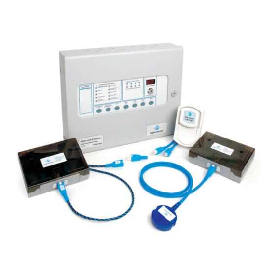
www.acornfiresecurity.com INSTALLATION INSTRUCTIONS Hydrosense Conventional Water Detection System Overview of the Hydrosense Water Detection System ..........2 Detection Components ......................3 Linear Detection- Hydrowire Cable ...................... 3 Linear Detection EOL ............................. 3 Linear Detection Connection Interface .................... 3 Floor Probe Junction Box .......................... 3 Point Detection Floor Probe ........................ 4 Control and Indicating Equipment of a Hydrosense System ........4 Control Panel (2 to 8 Zones) ........................ 4 Hydrosense Mimic Panels .......................... 4 System components: ............................ 5 System Options .............................. 5 Design & Planning ........................5 Design Notes .............................. 5 Design Guidelines ............................ 6 Hydrosense Floor Probe: . -
Page 3: Overview Of The Hydrosense Water Detection System
www.acornfiresecurity.com INSTALLATION INSTRUCTIONS Hydrosense Conventional Water Detection System Overview of the Hydrosense Water Detection System The Hydrosense water detection system is designed to detect the intrusion of water in concealed areas or any place where water penetration must be identified so that corrective action can be taken immediately. -
Page 4: Detection Components
www.acornfiresecurity.com INSTALLATION INSTRUCTIONS Hydrosense Conventional Water Detection System Detection Components Linear Detection- Hydrowire Cable Where floor areas, ducts and suspended ceilings need to be protected this is usually best achieved by installing lengths of Hydrowire. Hydrowire is a highly conductive cable extremely sensitive to moisture. -
Page 5: Point Detection Floor Probe
www.acornfiresecurity.com INSTALLATION INSTRUCTIONS Hydrosense Conventional Water Detection System Point Detection Floor Probe Where a requirement exists for more localised detection, such as HVAC plant, drip trays, elevator shafts and storage areas a floor probe (HS-WLDP) can be installed. As with the cable the detection of moisture triggers an alarm and is also monitored by the line fault circuit of the control panel. -
Page 6: System Components
www.acornfiresecurity.com INSTALLATION INSTRUCTIONS Hydrosense Conventional Water Detection System System components: Hydrowire (5 metre Length) HYDW-05 Hydrowire (10 metre Length) HYDW-10 End of Line Plug HS-HWCI-EOL Hydrowire Connection Box HS-HWCI Zone Extender (1 metre length) HY-ZB01 Zone Extender (3 metre length) HY-ZB03 Zone Extender (10 metre length) HY-ZB10... -
Page 7: Design Guidelines
www.acornfiresecurity.com INSTALLATION INSTRUCTIONS Hydrosense Conventional Water Detection System Maximum length of Hydrosense cable should be kept to 50 metres Maximum number of detectors per zone should not exceed 20. Only one remote indicator to each Hydrowire Connection Interface or Junction Box. Design Guidelines Hydrosense Floor Probe: Maximum recommended coverage:... -
Page 8: Panel Installation
www.acornfiresecurity.com INSTALLATION INSTRUCTIONS Hydrosense Conventional Water Detection System Panel Installation Safety Suppliers of articles for use at work are required under section 6 of the Health and Safety at Work act 1974 to ensure as reasonably as is practical that the article will be safe and without risk to health when properly used. -
Page 9: Removing The Front Facia
www.acornfiresecurity.com INSTALLATION INSTRUCTIONS Hydrosense Conventional Water Detection System It should be positioned in an accessible place as agreed with the end user. Suitable fixings should be used at all fixing points such that the control panel is securely mounted and is not liable to move once fixed. The control panel should not be mounted in another enclosure or near sources of excessive heat. - Page 10 www.acornfiresecurity.com INSTALLATION INSTRUCTIONS Hydrosense Conventional Water Detection System lift the fascia gently away from the box towards you. With the fascia removed there is much more room inside the panel for making off and dressing cables. When cabling work is complete the fascia can be re-fitted with the two countersunk screws and the red, green/yellow and black wires re-connected to the three way terminal block NOTE: It is most important that the polarity of the red and black wires are observed as...
- Page 11 www.acornfiresecurity.com INSTALLATION INSTRUCTIONS Hydrosense Conventional Water Detection System Figure 3 RS 485 Bus Bus connected devices are connected via a 2 core cable to the terminals marked RS485 + and – on the main control panel PCB. Up to 14 devices may be connected and each device has terminals for the incoming cables and outgoing cables.
- Page 12 www.acornfiresecurity.com INSTALLATION INSTRUCTIONS Hydrosense Conventional Water Detection System All repeaters are now configured and the control panel will report a fault if any repeaters that have been accepted become faulty or go off line. Ancillary Boards Connect the RS485 bus and power to each Ancillary board. Up to 7 Ancillary boards may be connected and each board has terminals for the incoming cables and outgoing cables.
-
Page 13: Control Relays
www.acornfiresecurity.com INSTALLATION INSTRUCTIONS Hydrosense Conventional Water Detection System Detection zone wiring The detection zones provide a nominal 24V DC to power the Hydrosense devices. The wiring is monitored for open and short circuit fault conditions by removing the 6K8 end of line monitoring resistors that are supplied fitted to the control panels’... -
Page 14: Access Level 2 Configuration Options
www.acornfiresecurity.com INSTALLATION INSTRUCTIONS Hydrosense Conventional Water Detection System Access level 2 configuration options Turn enable keyswitch to get to access level 2. OPERATION Press Mode button until the required function as detailed below appears in the 7 segment displays. For Zonal tests or Disablements, press the Select button to scroll to the required zone number then press enter. -
Page 15: Access Level 3 Configuration Options
www.acornfiresecurity.com INSTALLATION INSTRUCTIONS Hydrosense Conventional Water Detection System Access level 3 configuration options The Hydrosense control panel has many configuration options, which can be set at the time of commissioning to suit the requirements of the installation. These options are normally set once and will rarely need to change. - Page 16 www.acornfiresecurity.com INSTALLATION INSTRUCTIONS Hydrosense Conventional Water Detection System Table 1 Code FUNCTION COMMENTS CONFIGURATION UPDATE COUNT Number incremented each time access level 3 config changed SOUNDER DELAY TIME = 30 SECONDS Introduces a time delay before sounders operate. SOUNDER DELAY TIME = 1 MINUTE SOUNDER DELAY TIME = 2 MINUTES SOUNDER DELAY TIME = 3 MINUTES SOUNDER DELAY TIME = 4 MINUTES...
-
Page 17: Internal Switches
www.acornfiresecurity.com INSTALLATION INSTRUCTIONS Hydrosense Conventional Water Detection System ZONE 4 NON- SOUNDER MODE ZONE 5 NON- SOUNDER MODE ZONE 6 NON- SOUNDER MODE ZONE 7 NON- SOUNDER MODE ZONE 8 NON- SOUNDER MODE ZONE 1 30 SECOND INPUT DELAY Zone needs to be triggered for 30 seconds continuously before an alarm is generated, ZONE 2 30 SECOND INPUT DELAY programmable for each zone. -
Page 18: Internal Indicators
www.acornfiresecurity.com INSTALLATION INSTRUCTIONS Hydrosense Conventional Water Detection System Internal Indicators Mains fail Indicates that the 230V AC supply is not present and the system is running on standby batteries. If there is not a power cut, check the panels mains fuse. Batt Fail Indicates that the standby battery has become disconnected or that the charging circuit of the control panel has failed. -
Page 19: Hydrowire Installation And Commissioning
www.acornfiresecurity.com INSTALLATION INSTRUCTIONS Hydrosense Conventional Water Detection System Hydrowire Installation and Commissioning Hydrowire Installation HSHWI-100 Mount the Connection Interface to the area where the start of the Hydrowire is to be mounted. Wire the Connection Interface back to the Hydrosense Control Panel as shown in Hydrosense Wiring section. -
Page 20: Hydrowire Wiring
www.acornfiresecurity.com INSTALLATION INSTRUCTIONS Hydrosense Conventional Water Detection System Hydrowire Wiring The HS-HWCI Connection Interface allows the Hydrowire to be plugged in and provides the installer the option of connecting a Remote Indicator. The Zone In + and – terminals inside the Connection Interface must be connected via a 1.5mm 2-core cable (HYLCB) to the Z+ and Z- terminals at the control panel Figure 8... -
Page 21: Hydrowire Commissioning - Hshwc-100
www.acornfiresecurity.com INSTALLATION INSTRUCTIONS Hydrosense Conventional Water Detection System Hydrowire Commissioning – HSHWC-100 Once all terminations have been made and the system is powered, the Hydrowire is ready for testing. This is best achieved by dipping the forefinger and thumb into a cup of tap water, shaking off the excess drips and then gripping the Hydrowire firmly whilst rolling it slowly. -
Page 22: Hydrowire Layout
www.acornfiresecurity.com INSTALLATION INSTRUCTIONS Hydrosense Conventional Water Detection System Hydrowire Layout Figure 9 As it can be seen in Figure 9 that the Hydrowire cables are plugged together to provide 40m of detection cable Part Number Description Quantity HSCP-S-4-230 4 Zone Control panel HYDW-10 Hydrowire cable (10m) HS-HWCI-EOL... -
Page 23: Floor Probes Installation And Commissioning
www.acornfiresecurity.com INSTALLATION INSTRUCTIONS Hydrosense Conventional Water Detection System Floor Probes Installation and Commissioning Floor Probe Installation HSFPI -100 Mount the Junction Box to within 1 metre of where the Floor Probe is to be mounted. Wire the Junction Box back to the Hydrosense Control Panel as shown in Hydrosense Wiring section if it is the first Junction Box on the zone, otherwise wire from last Junction Box on the zone. -
Page 24: Floor Probe Wiring
www.acornfiresecurity.com INSTALLATION INSTRUCTIONS Hydrosense Conventional Water Detection System Floor Probe Wiring The HS-WLJB Junction Box allows the Probe to be plugged in and provides the installer the option of connecting a Remote Indicator. The Zone In + and – terminals inside the Junction Box must be connected via a 1.5mm core cable (HYLCB) to the Z+ and Z- terminals at the control panel. -
Page 25: Floor Probe Testing
www.acornfiresecurity.com INSTALLATION INSTRUCTIONS Hydrosense Conventional Water Detection System Floor Probe Testing (1) This is best achieved by wetting both of the brass contacts simultaneously with fresh water. (2) This should produce an immediate reaction at the control panel, the LED mounted on top of the probe, if fitted, the remote Indicator lamp and panel sounders. -
Page 26: Probe Layout
www.acornfiresecurity.com INSTALLATION INSTRUCTIONS Hydrosense Conventional Water Detection System Probe Layout Figure 11 Part Number Description Quantity HSCP-S-2-230 2 Zone Control panel HS-WLDP Hydrosense Floor Probe HS-WLJB Hydrosense Junction Box HSVS Voice Sounder Y7-12 7A backup batteries HYLCB 1.5mm 2-core cable LSZH (100m) Document Part No.
Need help?
Do you have a question about the hydrosense HSHWI-100 and is the answer not in the manual?
Questions and answers