
Related Manuals for Vimpex hydrosense IDAP-S-2-230

Summary of Contents for Vimpex hydrosense IDAP-S-2-230
- Page 1 www.acornfiresecurity.com Delivering a New Standard in Water Leak Detection Installation Instructions Issue 01 October 2018 www.acornfiresecurity.com...
-
Page 2: Table Of Contents
www.acornfiresecurity.com INSTALLATION INSTRUCTIONS Hydrosense ID Addressable Water Detection System Index 1. Introduction ............................. 5 2. Safety ................................ 5 3. Technical Specification ........................... 6 4. Mounting .............................. 6 4.1 Installation ............................. 7 5. Cabling ..............................8 ... - Page 3 www.acornfiresecurity.com INSTALLATION INSTRUCTIONS Hydrosense ID Addressable Water Detection System 15. Power Supply ............................20 15.1. Aux. 24V Supply ..........................20 15.2. 24V OUT Terminals ........................20 15.3. Remote PSU ..........................20 15.4. Battery Capacity ........................... 20 ...
- Page 4 www.acornfiresecurity.com INSTALLATION INSTRUCTIONS Hydrosense ID Addressable Water Detection System 18. Panel Settings ............................29 18.1. Contrast Adjust ..........................29 19. Panel Specification Summary ......................30 19.1. Recommended Cables ........................30 19.2. Sounder Load ..........................30 ...
-
Page 5: Introduction
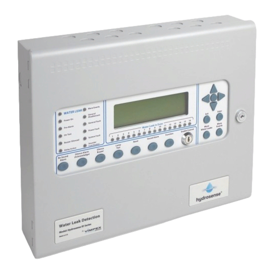
www.acornfiresecurity.com INSTALLATION INSTRUCTIONS Hydrosense ID Addressable Water Detection System 1. Introduction The Hydrosense ID is an addressable water leak detection and alarm control panel with 16 zonal LED indicators and is available in models with either 1 or 2 detection loops. Each loop can support up to 127 loop-powered I/O modules. -
Page 6: Technical Specification
www.acornfiresecurity.com INSTALLATION INSTRUCTIONS Hydrosense ID Addressable Water Detection System 3. Technical Specification Overall Size 385 mm x 310 mm x 90 mm Finish BS 00 A 05 mid grey fine texture Mains Supply 230 VAC, 50Hz +10% -15% (100 Watts maximum) Mains Supply fuse 1.6 Amp (F1.6A L250V) Power Supply rating Imax a... -
Page 7: Installation
www.acornfiresecurity.com INSTALLATION INSTRUCTIONS Hydrosense ID Addressable Water Detection System 4.1 Installation The installation of the panel should be carried out by qualified personnel only. The electronic components within the panel are vulnerable to physical damage and damage by electrostatic discharges. It is advisable to wear a wrist strap designed to prevent the build-up of static charges within the body, before handling any electronic circuit boards. -
Page 8: Cabling
www.acornfiresecurity.com INSTALLATION INSTRUCTIONS Hydrosense ID Addressable Water Detection System 5. Cabling It is advisable to fit cable glands and cables before re-fitting the outer cover and plate/circuit board assembly. Cables should be brought into the cabinet using the knockouts provided and where necessary, using couplers to maximise the space within the enclosure. -
Page 9: Connecting To The Panel
www.acornfiresecurity.com INSTALLATION INSTRUCTIONS Hydrosense ID Addressable Water Detection System 6. Connecting to the Panel All panel terminal block connections support cable with a maximum cross section capacity of 2.5 mm capacity. Care should be taken to use the correct sized terminal screwdriver and not to over tighten the screws. If stranded cables are used then care should be taken to ensure that all strands are contained in the terminal block and that there are not any loose strands that may cause short circuits to other terminals or cables. -
Page 10: Front Panel Controls
www.acornfiresecurity.com INSTALLATION INSTRUCTIONS Hydrosense ID Addressable Water Detection System 7. Front Panel Controls The front panel contains controls for operating and programming the panel. The “Lamp Test” and “Silence Buzzer” buttons can be operated at any time. (Access Level 1) The “More Leak Events”... -
Page 11: Powering The Panel
www.acornfiresecurity.com INSTALLATION INSTRUCTIONS Hydrosense ID Addressable Water Detection System 8. Powering the Panel Never connect batteries before applying mains power first. Ensure that the panel is free from swarf, wire ends, knockout blanks and any other debris. Ensure that all cable connections to loops, sounder circuits and other inputs or outputs being used are correct and that the wiring is formed tidily away from the surface of the circuit board before applying power. -
Page 12: Configuring The Panel (Autolearn - Initial Startup)
www.acornfiresecurity.com INSTALLATION INSTRUCTIONS Hydrosense ID Addressable Water Detection System It will not be possible to perform the Autolearn sequence or transfer a configuration into the panel from the PC (as described below) unless the configuration memory is “Write Enabled”. It is also necessary to operate the “Write Enable” switch whenever any changes are made to the configuration memory using the Access Level 3 “Edit Configuration”... -
Page 13: Configuring The Panel (From Pc)
www.acornfiresecurity.com INSTALLATION INSTRUCTIONS Hydrosense ID Addressable Water Detection System On a system, which has been Auto learned; inputs, outputs and field devices will be configured to the default settings. Some of these defaults may be altered at Access Level 3 on the control panel. All can be altered via the Loop Explorer PC (LE2) configuration utility. -
Page 14: Facilities Menu
www.acornfiresecurity.com INSTALLATION INSTRUCTIONS Hydrosense ID Addressable Water Detection System Once the file has been saved an option to use a dial up connection will be offered. If this facility is going to be used, select yes and enter the telephone number that will need to be dialled to connect to the panel. If this is not required select no. -
Page 15: Detection Circuits
www.acornfiresecurity.com INSTALLATION INSTRUCTIONS Hydrosense ID Addressable Water Detection System 10. Detection circuits Hydrosense ID control panels are configured to communicate using only Hydrosense ID loop components. Power is driven from the “LOOP OUT” terminals and is returned to the “LOOP IN” terminals, where it is monitored for detection loop continuity. -
Page 16: Fitting Additional Detection Circuit (Loop Card: Idap-Lec)
www.acornfiresecurity.com INSTALLATION INSTRUCTIONS Hydrosense ID Addressable Water Detection System 10.1. Fitting additional Detection Circuit (Loop Card: IDAP-LEC) On a single loop Hydrosense ID panel an additional detection circuit (loop card) can be fitted, it must be compatible with the existing detection circuit. Note: The system can only support a maximum of two loops. To fit the Loop Card, the control panel must have mains and battery power removed. -
Page 17: Panel Sounder Circuits
www.acornfiresecurity.com INSTALLATION INSTRUCTIONS Hydrosense ID Addressable Water Detection System 11. Panel Sounder Circuits Two conventional sounder circuits are provided in the panel, each fused at 1 Amp. A 10KΩ end of line resistor monitors the circuits for open and short circuit faults. Both circuits are configured to activate upon any Leak Detection condition and to de-activate when the “Silence Alarm/ Acknowledge”... -
Page 18: Remote I/O Serial Bus
www.acornfiresecurity.com INSTALLATION INSTRUCTIONS Hydrosense ID Addressable Water Detection System All inputs can be re-programmed to have a different action, delay, zone and location message using the Loop Explorer PC (LE2) configuration utility or front panel controls (at Access Level 3) To activate the inputs, the “0V”... -
Page 19: Way Sounder Board (Id-Sio-6S)
www.acornfiresecurity.com INSTALLATION INSTRUCTIONS Hydrosense ID Addressable Water Detection System 14.3. 6 way Sounder Board (ID-SIO-6S) The 6 way sounder board has 6 voltage reversing, monitored Sounder Outputs which can be programmed to operate as required on response to Alarms or Cause & Effects. The sounder board also have two programmable, volt free changeover relay contacts and two Opto-Isolated Inputs all of which are also fully programmable via the Loop Explorer PC (LE2) configuration utility. - Page 20 www.acornfiresecurity.com INSTALLATION INSTRUCTIONS Hydrosense ID Addressable Water Detection System 15. Power Supply The control panel is fitted with a 2.3 Amp power supply and battery charger capable of charging up to 9 Ah batteries. A separate power supply should be used if larger batteries are required. The power supply requires a 230 VAC mains connection to the fused, mains terminal block in the top left corner of the back box.
- Page 21 www.acornfiresecurity.com INSTALLATION INSTRUCTIONS Hydrosense ID Addressable Water Detection System PANEL TYPE QUIESCENT ALARM CURRENT CURRENT Single loop panel 0.13 A 0.3 A Two loop panel (Single Loop with Additional loop Card) 0.195 A 0.37 A To calculate the capacity of the batteries required the following formula should be used. (Quiescent Load (A) x 1.25) X Standby Period (hours) + ((Alarm Load x 1.75)/2) = Ah The maximum size of battery, which can be fitted inside standard control panels, is 9 Ah (2 x PBQ 9HR-12).
- Page 22 www.acornfiresecurity.com INSTALLATION INSTRUCTIONS Hydrosense ID Addressable Water Detection System 16. Programming via Loop Explorer PC (LE2) Configuration Utility Due to the use of the very latest microprocessor and memory technology, the Hydrosense ID Water Leak control Panel is an extremely powerful controller. As such, it can be programmed in an almost infinite number of ways, some of which will not give the visual and audible indications expected from a Water Detection system.
- Page 23 www.acornfiresecurity.com INSTALLATION INSTRUCTIONS Hydrosense ID Addressable Water Detection System 16.1.6. Access Level Code Changes The default codes to enter Access Level 2 and Access Level 3 can be changed via the Loop Explorer PC (LE2) configuration utility only. 16.1.7. Panel Text A forty-character message can be entered which is displayed when the control panel is in a quiescent condition.
- Page 24 www.acornfiresecurity.com INSTALLATION INSTRUCTIONS Hydrosense ID Addressable Water Detection System 16.2. Inputs To simplify programming and promote an easy understanding of the system, the operation of the Hydrosense ID panel has been designed around a very simple principle. This principle is that all inputs are handled in exactly the same way, whether they are from a loop device, a programmable input on the panel, an I/O board or the programmable pushbutton on the front panel.
- Page 25 www.acornfiresecurity.com INSTALLATION INSTRUCTIONS Hydrosense ID Addressable Water Detection System 16.2.5. Sound Alarm Action The Sound Alarm Action allows all sounder outputs and sounders to be operated continuously from an input anywhere on the system with the following response at the panel: COMMON WATER LEAK LED’s •...
- Page 26 www.acornfiresecurity.com INSTALLATION INSTRUCTIONS Hydrosense ID Addressable Water Detection System 16.3. Outputs Control of Outputs uses the same philosophy as that described for Inputs, i.e. all outputs are treated same, whether they loop controlled relays, panel sounder outputs, panel programmable relays, remote I/O board outputs panel mounted programmable...
- Page 27 www.acornfiresecurity.com INSTALLATION INSTRUCTIONS Hydrosense ID Addressable Water Detection System 16.3.3. Silenceable Silenceable is normally applicable to sounder outputs and ensures that the output switches off when the alarm is silenced/acknowledged by the front panel pushbutton or operation of an input that is configured as an Ack. Alarm (Acknowledge Alarm input) .
- Page 28 www.acornfiresecurity.com INSTALLATION INSTRUCTIONS Hydrosense ID Addressable Water Detection System 17. Cause & Effect Programming For more complex applications, it is often a requirement to control plant in the event of Water Leak situations to assist with shutdown of equipment or the water supply. Because the Hydrosense ID system has inherent flexibility, this is simple to achieve by applying Cause &...
- Page 29 www.acornfiresecurity.com INSTALLATION INSTRUCTIONS Hydrosense ID Addressable Water Detection System 18. Panel Settings 18.1. Contrast Adjust The viewing angle/contrast of the Hydrosense ID front panel display may be adjusted by turning the “CONTRAST” adjust potentiometer. The contrast adjust potentiometer can be accessed by opening the front cover of the control panel and is labelled “CONTRAST”.
- Page 30 Battery low indication 21V, Earth fault indication < 30 KΩ +28 V or 0 V to earth. 19.5. Field Devices Vimpex 127 devices per loop Per 1 loop panel 127 ID Addressable modules Per 2 loop panel 254 ID Addressable modules Sub-address total 800 addresses and sub-address limit per panel.
- Page 31 www.acornfiresecurity.com INSTALLATION INSTRUCTIONS Hydrosense ID Addressable Water Detection System 19.10. Fuse Ratings All panel power supplies, monitored outputs and auxiliary power outputs are protected by non-serviceable self resetting electronic fuses. Detection circuits are protected using digital current monitoring circuits and FET switching techniques. The Hydrosense ID panel has a serviceable fuse to protect the incoming mains supply.
Need help?
Do you have a question about the hydrosense IDAP-S-2-230 and is the answer not in the manual?
Questions and answers