Advertisement
Quick Links
2019/08/21 02:55
Spectroscopy
Module
Model No. D2-210
Document Revision: 1
Document Last Updated on 2019/06/25 22:53
Please read
Limited Warranty
Warnings and Cautions
D2-210. D2-210
website
Description
The D2-210 saturated absorption spectroscopy module provides error signals derived from saturated
absorption spectroscopy of atomic rubidium, cesium, or potassium. It contains a vapor cell, internal
temperature controller, balanced photodetectors, and optics. Temperature control stabilizes the
number density of atoms in the cell, and a balanced photodetection circuit compensates for intensity
drifts giving stable control over the lock point for side locking applications. The photodiode output is
shot-noise limited out to greater than 5 MHz for photocurrents of 50 μA and above. The high
bandwidth of the feedback enables tight solid locking that is immune to vibrations and shock. The
D2-210 is powered by a cable that plugs into the power connectors on any D2 series electronics
module.
The D2-210 is a significant upgrade to the D2-110 incorporating many suggestions from our
customers:
The module is magnetically shielded to allow close placement to the D2-100 DBR laser module.
An adjustable λ/2 waveplate enables the user to control light level pickoff over a wide range of
input power levels.
In addition to rubidium and cesium, the D2-210 can now be configured with potassium.
Ordering options exist for Doppler subtraction and fiber coupling.
Future ordering options will include lock signals derived by DAVLL and Zeeman Modulation
spectroscopy.
Purchase Includes
D2-210 Spectroscopy Module
VPN00463 SMA cable (6ft)
VPN00410 Hirose-to-D Sub 9-pin (shipped under separate line item; specify for use with D2)
VPN00475 Hirose-to-Hirose power cord (shipped under separate line item; specify for use with
ICE)
VPN00367 Adjustment tool
Product Manuals - https://www.vescent.com/manuals/
and
General
prior to operating the
and
data
sheet.
1/12
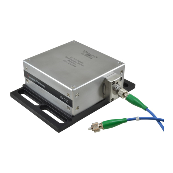
D2-210 Spectroscopy Module with fiber coupling
option
Spectroscopy Module
Advertisement

Related Manuals for Vescent D2-210

Summary of Contents for Vescent D2-210
- Page 1 5 MHz for photocurrents of 50 μA and above. The high bandwidth of the feedback enables tight solid locking that is immune to vibrations and shock. The D2-210 is powered by a cable that plugs into the power connectors on any D2 series electronics module.
-
Page 2: Absolute Maximum Ratings
Tab. 2 Powering the D2-210 The D2-210 requires +5 and ±15 VDC and ground to operate. The power input is via a female 6-pin Hirose connector HR10A-7TR-6SA(73). Depending on your order configuration, you should have received a power cable with this connector on one end and either the same on the other end (typically for use with ICE products) or a DB-9 connector (for use with D2-products). - Page 3 2019/08/21 02:55 3/12 Spectroscopy Module Fig. 1: Beam path and component map Product Manuals - https://www.vescent.com/manuals/...
- Page 4 The beam diameters were designed to provide enough photocurrent (~50-100μA) to give shot-noise- limited performance out to 5 MHz while limiting saturation broadening. For Vescent's DBR lasers, the bandwidth is useful to provide for tight and stable locking by feedback to injection current.
-
Page 5: Inputs, Outputs, And Controls
Tab. 3 Note: When powering the D2-210 with supplies other than a D2-005, pins 5 and 6 can be placed between 7-15 V. They need not be symmetric, but both supply rails are always required. See D2-005 manual for pin out on D-Sub 9-pin connector. - Page 6 (clockwise) will result in faster temperature settling until oscillation occurs. Temperature Bias Adj. [Note: this adjustment is only available on older D2-210 models.] For the Doppler subtraction option this control enables the user to input a small temperature difference between the reference and signal vapor cells.
- Page 7 Fig. 5: Half wave plate adjuster Quick Setup Guide Set the D2-210 in the beam path of the laser so that the beam goes through the center of the input and output holes. Loosely apply the four 1/4-20 mounting screws and washers to affix the...
- Page 8 Using the cable provided, connect the 8-pin circular Hirose connector to the D2-210 and connect the D-sub 9-pin connector to a free power connector on the D2-005 or other Vescent electronics module. If you are using an alternate power supply, refer to the table above for correct voltage input connections.
- Page 9 PBS. At this point, the beams should be well aligned and overlapped. Place a viewing card in front of the Reference photodiode as shown below. Product Manuals - https://www.vescent.com/manuals/...
- Page 10 Last update: 2019/06/25 22:53 d2:spectroscopy_module_210 https://www.vescent.com/manuals/doku.php?id=d2:spectroscopy_module_210 Adjust the λ/2 waveplate to give approximately 1 Volt at the output SMA (with Reference beam blocked). Scan the laser until the Doppler broadened transitions are visible. Doppler-free hyperfine transitions should be clearly evident. For Rb, the cycling transition should have a depth between 20 and 50 mV.
- Page 11 2019/08/21 02:55 11/12 Spectroscopy Module Fig. 7: Non-Doppler subtracted side- and peak-lock spectra Fig. 8: Doppler subtracted side- and peak-lock spectra Product Manuals - https://www.vescent.com/manuals/...
- Page 12 Last update: 2019/06/25 22:53 d2:spectroscopy_module_210 https://www.vescent.com/manuals/doku.php?id=d2:spectroscopy_module_210 From: https://www.vescent.com/manuals/ - Product Manuals Permanent link: https://www.vescent.com/manuals/doku.php?id=d2:spectroscopy_module_210 Last update: 2019/06/25 22:53 https://www.vescent.com/manuals/ Printed on 2019/08/21 02:55...
Need help?
Do you have a question about the D2-210 and is the answer not in the manual?
Questions and answers