Table of Contents
Advertisement
Available languages
Available languages
Quick Links
FB052
Ident.-Bezeichnung
Ident. designation
Anleitung
Ariston LAN
Manual
Format:
A6Q
Format:
Herausgabeindex:
20140411
Issue index:
Kundenfreigabe
Customer approval
erteilt am:
Date of approval:
Bemerkungen:
Remarks:
Urheberrecht / Copyright
Das Copyright für die von der Firma RESOL – Elektronische Regelungen GmbH selbst erstellten Objekte, Dokumente, Grafiken, Abbildungen, Tondokumente,
Videosequenzen,Texte etc. bleibt allein bei der Firma RESOL. Eine Vervielfältigung, Weitergabe an Dritte, Veränderung der Inhalte oder die Verwendung in
elektronischen oder gedruckten Publikationen ist ohne ausdrückliche Zustimmung der Firma RESOL nicht gestattet.
Please note that RESOL – Elektronische Regelungen GmbH owns the sole copyright on objects, documents, graphics, pictures, audio and video documents, texts,
etc. published and created by RESOL – Elektronische Regelungen GmbH. Copying, distribution to third parties, changing the contents or using these contents in
electronic or printed publications is not permitted without the explicit approval by RESOL.
Kundenfreigabe: Anleitungen
Customer approval: Manuals
Art.-Nr.:
11206565
Art. no.:
Änderungsindex:
1.1
Change index:
ja
/
yes
nein
/
Unterschrift:
Signature:
RESOL-Basis-Art.-Nr.:
Basic RESOL art. no.:
Datum:
Date:
Bearbeiter:
Issuer:
no
Name in Druckbuchstaben:
Name in block letters:
05.09.2014
K. Erhardt
Advertisement
Chapters
Table of Contents

Subscribe to Our Youtube Channel
Related Manuals for Resol Solar Manager Pro to LAN


Summary of Contents for Resol Solar Manager Pro to LAN
- Page 1 Please note that RESOL – Elektronische Regelungen GmbH owns the sole copyright on objects, documents, graphics, pictures, audio and video documents, texts, etc. published and created by RESOL – Elektronische Regelungen GmbH. Copying, distribution to third parties, changing the contents or using these contents in...
- Page 2 Interface adapter Mounting Connection Installation Adaptateur interface Montage Raccordement Commande Adaptador de interfaz Montaje Conexionado eléctrico Instalación Adattatore di interfaccia Montaggio Manual Collegamento Installazione Manuel Manual Manuale...
-
Page 3: Table Of Contents
Safety advice Table of contents Technical data ..........18 Please pay attention to the following safety advice in order to avoid danger and damage to people and property. Mounting ............18 Electrical connection ........19 Description of symbols Network settings ..........21 ATTENTION! Warnings are indicated with a warning tri- LED at the front of the housing ....26 angle! Glossary ............27... - Page 4 Proper usage • Full version of the RSC software included on CD-ROM The Solar Manager Pro to LAN interface adapter is de- The Solar Manager Pro to LAN interface adapter may only signed for the connecting the controller directly to a PC or be used for connecting an electronic controller for solar router.
-
Page 5: Technical Data
, LAN interface ® Î Drill and prepare the hole with a wall plug and screw. Î Hang the device onto the screw. Solar Manager Pro to LAN Î Mark the position for the mounting screw (centres Input: 12V / 0,5 A 5.5 x 2.5 mm... -
Page 6: Electrical Connection
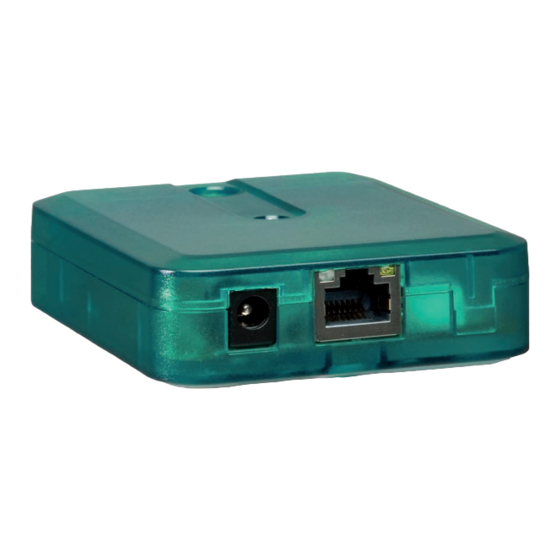
Front view Î Finish terminal connection and close the housing before establishing the mains connection! The Solar Manager Pro to LAN interface adapter needs a Hanging mains, a VBus and a LAN connection to function. To install ®... - Page 7 Interior view of the Solar Manager Pro to LAN adapter ATTENTION! Low voltage cables must not run together in a cable conduit with cables carrying a RJ45 LAN connector Status-LEDs Mains connector higher voltage than 50 V. Î Always route high and low voltage cables separately! Î...
-
Page 8: Network Settings
Note The Web interface has the following functions: In MS Windows from version 7 on, UPnP access is • Displaying the status of the Solar Manager Pro to LAN activated by default. In earlier versions, UPnP access interface adapter. must be activated manually. - Page 9 The default password for the authentication enquiry of the Î Enter the desired name into the Module Name in- Solar Manager Pro to LAN interface adapter is vbus. It can put field. be changed in order to prevent unauthorised access.
- Page 10 Reset If the password for the Solar Manager Pro to LAN interface adapter is lost, the device has to be manually reset to the factory settings. In order to conduct a reset, proceed as follows: Î Open the housing (see page 4).
- Page 11 Using a dynamic Domain Name Server (DynDNS) 3. In order to access the router via the Internet, the user has to enter the DynDNS Internet address into the In- ternet browser. Using a static Internet IP address DynDNS Schematic representation: Remote access to the interface adapter, router with DynDNS address.
- Page 12 3. The router registers at the ISP with the static IP address. The Solar Manager Pro to LAN interface adapter commu- nicates via the following ports: 4. In order to access the router via the Internet, the user • Web interface port: 443 (adjustable, default port: 443) has to enter the static Internet address into the Internet •...
-
Page 13: Led At The Front Of The Housing
LED at the front of the housing At the RJ45 LAN connector there are 2 status LEDs which The Solar Manager Pro to LAN interface adapter has 1 bi- indicate the status of the network connection: coloured LED at the front of the housing and 2 LEDs at the RJ45 LAN connector. - Page 14 © All contents of this document are protected by copyright.
- Page 15 Recommandations de sécurité Sommaire Veuillez lire attentivement les recommandations de sécu- Caractéristiques techniques .......32 rité suivantes afin d’éviter tout dommage aux personnes Montage ............32 et aux biens. Branchement électrique ......33 Installation dans le réseau ......35 Explication des symboles LED sur la partie supérieure du boîtier..40 ATTENTION ! Les messages d’avertissement sont pré- Glossaire ............41...
- Page 16 Déclaration de conformité CE L’adaptateur interface Solar Manager Pro to LAN peut se Le marquage „CE“ est apposé sur ce produit, connecter à tous les régulateurs dotés d’un VBus ®...
-
Page 17: Caractéristiques Techniques
, RJ45 LAN ® Î Accrochez le boîtier à la vis supérieure et marquez le point de fixation inférieur (distance entre les deux Solar Manager Pro to LAN trous : 70 mm). Input: 12V / 0,5 A 5.5 x 2.5 mm Î... -
Page 18: Branchement Électrique
Branchement électrique ATTENTION ! Décharges électrostatiques ! partie supérieure Des décharges électrostatiques peuvent en- du boîtier dommager les composants électroniques ! Î Déchargez-vous de l’électricité statique ! vis de fermeture ATTENTION ! Court-circuit ! Des décharges électrostatiques peuvent en- orifice pour la dommager les composants électroniques ! vis de fixation Î... - Page 19 Vue intérieure de l’adaptateur Solar Manager Pro to LAN ATTENTION ! L’installation de câbles basse tension et de câbles trasmettant une tension supérieure LED d’indication à 50 V dans un même caniveau risque connecteur de l’état fonction- d’endommager l’appareil. pour l’adapta-...
-
Page 20: Installation Dans Le Réseau
Interface Web Installation dans le réseau L’adaptateur interface Solar Manager Pro to LAN se confi- Lorsque l’accès UPnP est activé, le système d’exploitation gure sur l’interface Web. reconnaît l’adaptateur interface Solar Manager Pro to LAN L’interface Web est intégrée dans l’adaptateur interface et automatiquement ;... - Page 21 • Changer le nom et le mot de passe de l’adaptateur inter- En cas d’oubli du mot de passe, rétablissez les réglages face Solar Manager Pro to LAN. d’usine. Pour plus d’informations, voir page 21. • Rétablir les réglages d’usine de l’adaptateur interface Solar Manager Pro to LAN.
- Page 22 Attribuer une adresse fixe au routeur Pour pouvoir accéder au router et à l’adaptateur interface Solar Manager Pro to LAN connecté à celui-ci sur Internet, le routeur doit avoir une adresse fixe. Attribuez une adresse internet fixe au routeur avec en uti- lisant l’une des possibilités suivantes : •...
- Page 23 3. Pour accéder au routeur sur Internet, saisir l’adresse Utiliser un Domain Name Server dynamique (DynDNS) Internet DynDNS sur le navigateur internet. Utiliser une adresse Internet fixe DynDNS Représentation schématique : accès à distance à l’adaptateur interface VBus /LAN, routeur avec une adresse DynDNS ®...
- Page 24 Le routeur s’inscrit auprès du FAI avec l’adresse IP L’adaptateur interface Solar Manager Pro to LAN com- fixe. munique par le biais des ports suivants: • Port interface Web: 443 (réglable, réglage d’usine Pour accéder au routeur sur Internet, saisir port: 443) l’adresse IP sur le navigateur Internet.
-
Page 25: Led Sur La Partie Supérieure Du Boîtier
LED d’indication d’état sur le connecteur RJ45 LED sur la partie supérieure du boîtier L’adaptateur interface Solar Manager Pro to LAN est doté Le deux LED situées sur le connecteur RJ45 LAN indiquent d’une LED bicolore sur la partie supérieure du boîtier et l’état de la connexion réseau :... - Page 26 © Tous les contenus du présent document sont couverts par des droits d‘auteur...
- Page 27 Contenido Advertencias de seguridad Por favor, preste atención a las siguientes advertencias de Datos técnicos ..........40 seguridad para evitar riesgos, daños personales y materia- Montaje ............40 les. Conexiones eléctricas........41 Configuración de la red. ......43 Explicación de los símbolos LED frontal de la carcasa ......48 ¡ATENCIÓN! ¡Las advertencias se muestran con un triángulo de alerta! Gracias por comprar este producto.
- Page 28 • Acceso a los datos del sistema a través de la red Uso adecuado • Parametrización a distancia del controlador vía VBus ® El adaptador de interfaz Solar Manager Pro to LAN puede • software de RSC incluido en CD-ROM utilizarse para conectar un dispositivo equipado con VBus ®...
-
Page 29: Datos Técnicos
, puerto LAN ® Î Sobre esta, realice el agujero con un taladro colocando seguidamente el taco y el tornillo. Solar Manager Pro to LAN Input: 12V / 0,5 A Î Cuelgue el equipo en el tornillo superior. Marque el 5.5 x 2.5 mm... -
Page 30: Conexiones Eléctricas
Î Conecte la alimentación solamente si los cables están conectados y la tapa cerrada. Punto de El adaptador de interfaz Solar Manager Pro to LAN requie- sujeción re, un VBus - y una red de conexión LAN. Para conectar el ®... - Page 31 Î Conecte el cable de red LAN que incluye el suminis- tro. Î Conecte el transformador a un enchufe de red eléc- trica. El adaptador de interfaz Solar Manager Pro to LAN, ahora está listo para su uso. Tecla reset Clema para el...
-
Page 32: Configuración De La Red
4.1 Encontrar el adaptador de interfaz Solar Manager Pro to LAN en la red local Si el adaptador de interfaz Solar Manager Pro to LAN no se de- tecta automáticamente, puede utilizar el software Device-Dis- cobery-Tool incluida en el CD-ROM de suministro. Para utilizar... - Page 33 Pro to LAN bajo el cual aparecerá en la red. LAN mediante el software RSC / RPT! La contraseña por defecto para la consulta de autentica- ción del adaptador de interfaz Solar Manager Pro to LAN es vbus. Ésta se puede cambiar para impedir accesos no autorizados.
- Page 34 Î Introduzca el nuevo nombre en el campo Nombre Î Después que se haya completado el reinicio, cierre la del módulo. cubierta nuevamente (vea la página 28). Î Haga clic en OK. El botón reset restablece los ajustes de fábrica del disposi- tivo.
- Page 35 Al router se le puede asignar una dirección fija desde In- obtener una dirección de Internet DynDNS. Recibirá ternet de dos formas: una dirección de Internet DynDNS y los datos necesa- rios para el acceso. • Mediante un servidor dinámico de nombres de dominio (DynDNS) 2.
- Page 36 En este ejemplo (ver tabla abajo), se han introducido 3 adap- el “port forwarding” en el router. El adaptador de interfaz tadores de interfaz Solar Manager Pro to LAN y se han asig- nado un puerto para la interfaz Web y un puerto para el software ServiceCenter para cada de los adaptadores.
-
Page 37: Led Frontal De La Carcasa
5.1 LEDs de estado del puerto LAN RJ45 En el conector LAN RJ45, hay 2 LEDs que indican el estado El adaptador de interfaz Solar Manager Pro to LAN tiene 1 LED bicolor en la parte frontal de la carcasa y 2 LEDs en de la conexión de red:... - Page 38 © El contenido del presente documento está protegido por derechos de autor.
- Page 39 Indice Avvertenze per la sicurezza Osservare queste avvertenze per la sicurezza per esclude- 1 Dati tecnici ............52 re pericoli e danni a persone e materiali. 2 Montaggio ............52 3 Collegamento elettrico ........53 Spiegazione dei simboli 4 Installazione nella rete ........55 5 LED sulla parte superiore dell’apparecchio..60 ATTENZIONE! Le avvertenze sono contrassegnate da...
- Page 40 Il prodotto è conforme alle direttive rilevanti ed qualsiasi PC collegato alla rete. L’adattatore di interfaccia è munito della marcatura CE. La dichiarazione di Solar Manager Pro to LAN è in grado di connettersi a tutti conformità può essere richiesta dal fabbricante. i controller con VBus...
-
Page 41: Dati Tecnici
® , porta LAN cedere conformemente alle seguenti indicazioni: Î Segnare il punto di sospensione, eseguire il relativo Solar Manager Pro to LAN foro ed inserirci il tassello e la vite corrispondenti Input: 12V / 0,5 A 5.5 x 2.5 mm compresi nella fornitura. -
Page 42: Collegamento Elettrico
Î Prima di allacciare l’adattatore alla rete elettrica, provvedere al colle- Sospensione gamento dei morsetti e chiudere il suo involucro! Il Solar Manager Pro to LAN richiede una rete elettrica di alimentazione , un VBus e una connessione LAN. Il corpo ® Cavità per i dell’apparecchio deve essere aperto per l’installazione della... - Page 43 Il Solar Manager Pro to LAN è ora pronto per il funzio- namento. ATTENZIONE! L’installazione di linee a bassa tensione Vista interna del Solar Manager Pro to LAN con linee che portano più di 50 V nella stessa canalizzazione può causare danni...
-
Page 44: Installazione Nella Rete
4.1 Trovare VBus nelle rete / LAN ® Se il Solar Manager Pro to LAN non viene riconosciuto au- tomaticamente, utilizzare lo strumento Device Discovery che è incluso nel CD-ROM. Per poter utilizzare il dispositi- Per l‘autenticazione, immettere i seguenti dati:... - Page 45 Senza password non è possibile accedere all‘apparecchio. sere realizzate le seguenti operazioni: Î Annotare la nuova password e conservala in luogo • Assegnare al Solar Manager Pro to LAN un indirizzo IP sicuro! statico. Se è stata dimenticata la password, effettuare un reset.
- Page 46 4.5 Reset 4.6 Accesso via Internet all’adattatore di interfaccia Solar Manager Pro to LAN Se si è persa la password per il Solar Manager Pro to LAN deve essere eseguito un reset. Per eseguire un ripristino, procedere come segue Î Aprire il Solar Manager Pro to LAN (vedi pagina 40).
- Page 47 4.7 Impiegare un Domain Name Server dinamico 4.8 Utilizzare un indirizzo IP Internet fisso (DynDNS) DynDNS Solar Presentazione schematica: Accesso remoto al Manager Solar Presentazione schematica: Accesso remoto al Manager Pro to LAN e router con indirizzo DynDNS. Pro to LAN e router con indirizzo IP fisso. Nota Esiste la possibilità...
- Page 48 Nota come segue: Non tutti i router supportano la deviazione della Î Assegnare al Solar Manager Pro to LAN tramite il porta. Per ulteriori informazioni, riportarsi alla do- menu di configurazione del router un indirizzo IP fisso cumentazione del router.
-
Page 49: Led Sulla Parte Superiore Dell'apparecchio
5.1 LED di stato sul connettore LAN RJ45 Sul connettore RJ45 LAN sono situati 2 LED di stato. Visua- Il Solar Manager Pro to LAN dispone di un LED bicolore lizzano lo stato della connessione di rete. nella parte superiore e due LED sulla porta LAN RJ45 bi- colori. - Page 50 © Il contenuto del presente documento è coperto da diritto d’autore.
- Page 51 Ariston Thermo SpA Chaffoteaux sas Ariston Thermo Portugal Viale Aristide Merloni 45 Le Carré Pleyel - 5 rue Pleyel Equipamentos Termodomesticos, 60044 Fabriano (AN) Italy 93521 Saint Denis Cedex Sociedade Unipessoal, Lda Telefono 0732 6011 Tél. 01 55 84 94 94 Zona Industrial da Abrunheira Fax 0732 602331 Fax 01 55 84 96 10...
Need help?
Do you have a question about the Solar Manager Pro to LAN and is the answer not in the manual?
Questions and answers