Advertisement
Quick Links
Advertisement

Related Manuals for ELBO CONTROLLI SETHY SIX


Summary of Contents for ELBO CONTROLLI SETHY SIX
- Page 1 INSTALLATION, OPERATION AND MAINTENANCE MANUAL rev 1.0 05/13...
- Page 2 1 GENERAL INDEX ELBO CONTROLLI srl SETHY SIX GENERAL INDEX 1 GENERAL INDEX............................2 2 CERTIFICATION ..............................4 3 DISMALTING..............................5 4 PRESENTATION...............................6 4.1 General Features............................6 4.2 Technical features............................6 5 WARNINGS...............................8 5.1 Introduction..............................8 5.2 Purpose...............................8 5.3 Font characters and heading layout.......................8 6 PREPARATION AND INSTALLATION......................10 6.1 Packing list..............................10...
- Page 3 1 GENERAL INDEX ELBO CONTROLLI srl SETHY SIX 9.8.5 Manual acquisition of angles....................56 9.8.6 Manual radii acquisition......................58 9.8.7 Radii and angles checking with mobile grid................59 9.8.8 Region of Interest........................62 9.9 Tool inspection............................63 10 MACHINE ORIGINS.............................66 10.1 NC machine origins..........................66 10.2 Introduction.............................67 10.3 Machine origin entering...........................68...
- Page 4 SETHY SIX CERTIFICATION The manufacturer, ELBO CONTROLLI S.r.l., under its own responsibility, DECLARES THAT: the SETHY SIX presetter conforms to the following safety standards where enforceable: 2006/42/CE harmonized standards EN ISO 12100-1, EN ISO 12100-2 2004/108/CE harmonized standards EN61326-1, EN55011 ISM (group 1, class A),...
- Page 5 3 DISMALTING ELBO CONTROLLI srl SETHY SIX 3 DISMALTING Information obligations to the end-users DISPOSAL OF WASTE MATERIALS INFORMATION FOR PROFESSIONAL USERS As per the 200/95/EC, 2002/96/EC and 2003/108/EC Directives, concerning the reduction in the use of hazardous substances in electrical and electronic apparatuses, as well as the disposal of waste materials.
- Page 6 4 PRESENTATION Thank you for purchasing ELBO CONTROLLI’s SETHY SIX Presetter (from now on referred to as SETHY SIX). You will certainly have great satisfaction using the SETHY SIX and you will increase the profitability of your NC machines SETHY SIX Presetters have been manufactured in compliance with ergonomic and simplicity principles and offer outstanding technological solutions.
- Page 7 Magnetic chip code-holders (Balluff for example, hardware not included) • Multi-cutting tools • ELBO CONTROLLI linear Transducers in optical glass type SLIDE 371 certified HP laser • Axes resolution: X= 1 µ m, Z= 1 µ m • Anti-dust cover provided for when not in use.
- Page 8 Purpose The aim of the manual is to allow the SETHY SIX Presetter operator to become acquainted with the machine’s operating directions, routine and non-routine maintenance and the proper operating procedures and to show all the required necessary actions from the presetter introduction until its disposal.
- Page 9 5 WARNINGS ELBO CONTROLLI srl SETHY SIX ....• step 4 Notes or instructions are identified using the following format: ✔ Note or instructions of particular interest. Page 9 of 96...
-
Page 10: Preparation And Installation
6 PREPARATION AND INSTALLATION ELBO CONTROLLI srl SETHY SIX PREPARATION AND INSTALLATION Packing list Before proceeding with preparation and installation, check that the tool presetter packaging contains the following components: PRESET MOD. SETHY SIX ROTATING SPINDLE ISO 30 ISO 40... - Page 11 Any other use is to be considered improper and compromising the operator’s safety. ✔ The SETHY SIX Presetter is to be handled by a single person in conditions of tested and controlled efficiency, in respect of all procedures described in this manual.
- Page 12 6 PREPARATION AND INSTALLATION ELBO CONTROLLI srl SETHY SIX Installation After the machine has been transferred to the installation site, the unpacking procedure must be followed with reference to the attached sheet. As for packing, the reverse procedure must be followed.
- Page 13 6 PREPARATION AND INSTALLATION ELBO CONTROLLI srl SETHY SIX Figure 2: Unpacking instructions Page 13 of 96...
- Page 14 6 PREPARATION AND INSTALLATION ELBO CONTROLLI srl SETHY SIX Figure 3: Unpacking instructions Page 14 of 96...
- Page 15 6 PREPARATION AND INSTALLATION ELBO CONTROLLI srl SETHY SIX Page 15 of 96...
- Page 16 6 PREPARATION AND INSTALLATION ELBO CONTROLLI srl SETHY SIX Page 16 of 96...
- Page 17 6 PREPARATION AND INSTALLATION ELBO CONTROLLI srl SETHY SIX 6.5.1 Machine stabilisation and electrical connection Loosen the foot fixing screw, by introducing a 6mm ring spanner/Allen key (B) in the hole at the rear of the machine. Introduce the 6mm hex Allen key (A) into the hole on the upper level of the machine and rotate until the machine is stable.
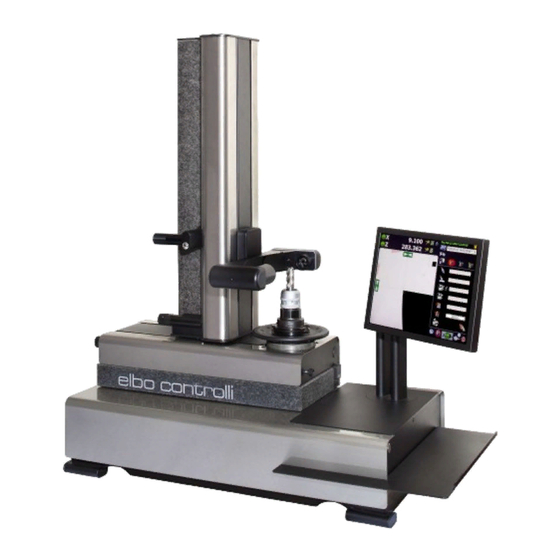
- Page 18 6 PREPARATION AND INSTALLATION ELBO CONTROLLI srl SETHY SIX 212V camera system Tools measurement illuminator Rapid movement handle Monitor LCD 15” Touch Screen Interchangeable spindle holder Shelf C-MOS image Axes pneumatic sensor board clamping button (rapid movements) Z axis micrometical...
- Page 19 6 PREPARATION AND INSTALLATION ELBO CONTROLLI srl SETHY SIX Annular illuminator Pneumatic pressure C-MOS lens adjuster image sensor Pneumatic feeding inlet Start button Pneumatic feeding filter USB communication ports Monitor LCD 15” inclination adjustment Power supply input 24 VDC ON/OFF switch...
- Page 20 Pneumatic circuit: compressed air between 5 and 6 bar. Machine DNA DNA is a service provided by Elbo Controlli for machines manufactured from January 2013. It consists of a QR code through which you can access a dedicated webpage for your Presetter.
- Page 21 Data regarding the test reports are protected, as indicated above, by an access password which is the numeric part of your Elbo Controlli client number. If you don’t have one, you can obtain it by sending an email to this email address: sales@elbocontrolli.it...
-
Page 22: Main Controls
7 MAIN CONTROLS ELBO CONTROLLI srl SETHY SIX MAIN CONTROLS Start Turn the switch, placed on the back panel, to the ON position. Push the start button on the right hand side of the machine. If the button is illuminated, the electronics is on. - Page 23 7 MAIN CONTROLS ELBO CONTROLLI srl SETHY SIX All functions can be controlled by touching the buttons on the Touch Screen Monitor. ✔ For best performance of the Touch Screen Monitor use the stylus included. To insert data, touch the monitor twice on the area of interest to visualise a keyboard (touch once to select the area and twice to visualise the keyboard), which can be numeric or alphanumeric, depending on requirements.
- Page 24 7 MAIN CONTROLS ELBO CONTROLLI srl SETHY SIX Operative areas Here are the operative areas found on the main screen and their functions. The screen can be basically divided into 4 main parts: Upper left quadrant: information about measurement and measurement taking...
- Page 25 7 MAIN CONTROLS ELBO CONTROLLI srl SETHY SIX Absolute/incremental commutation procedure The icon indicates that the corresponding axis is in Absolute mode. By touching the key you commute the desired axis in incremental mode as shown in the following example about the “X”...
- Page 26 7 MAIN CONTROLS ELBO CONTROLLI srl SETHY SIX Manual input of axes values Input value Touch Screen Keyboard for values input Touch the area of the screen where the value has to be inserted in order to display the numeric keyboard which enables you to insert the value.
- Page 27 7 MAIN CONTROLS ELBO CONTROLLI srl SETHY SIX Attention: only when there is no active machine origin (DEFAULT MACHINE active), will the set value be the new reference of the DEFAULT MACHINE overwriting the existing one. In this case the display is white and the measurement mode is absolute.
- Page 28 7 MAIN CONTROLS ELBO CONTROLLI srl SETHY SIX Bottom left quadrant: where the image coming from the camera is visualised, approx. 6,4 x 6,4mm. X and Z axes focusing bar Collimation indicator Fixed grid Tool shape In this area all functions of the camera will be available at any time: Fixed grid, angle grid, focusing bars, collimation/autocollimation indicators, automatic acquisition or manual measurement of angles and radii, tool inspection, digital/analogical visual, tool profile layout.
- Page 29 Date and time are given by the operative system. Touch the Elbo Controlli logo to access the Presetter Sethy SIX setup page. Touch the machine origin key (active after the acquisition of the zero axis) to access the creation, modification and cancellation functions of machine origin.
- Page 30 7 MAIN CONTROLS ELBO CONTROLLI srl SETHY SIX Bottom right quadrant where you can manage rapid label printing, machine origin and tool set. Rapid label printing Tool set Machine origins management management Page 30 of 96...
- Page 31 7 MAIN CONTROLS ELBO CONTROLLI srl SETHY SIX Lastly, in the bottom right quadrant you can find the “Spindle Index” function key (if the machine has this option) and the logout software key. Spindle index Close program (optional) Spindle functions 7.3.1...
- Page 32 7 MAIN CONTROLS ELBO CONTROLLI srl SETHY SIX 7.3.3 Spindle index (option) The Spindle Index function can be found only in those machines equipped with this option; it enables you to orientate and mechanically lock the spindle in 4 positions every 90°...
- Page 33 7 MAIN CONTROLS ELBO CONTROLLI srl SETHY SIX Moving the axes simultaneously enables you to reach the measurement area of the tool faster, while the lock/unlock function enables only one axis to be moved by keeping the other still. Figura 14: Axis lock keys...
-
Page 34: Preliminary Operations
SETHY SIX PRELIMINARY OPERATIONS Axes reference points When Sethy Six is switched on, it will automatically look for axes reference points, engraved on the measurement optical scales. In these fixed positions, the software will indicate the origin of any NC machine. - Page 35 8 PRELIMINARY OPERATIONS ELBO CONTROLLI srl SETHY SIX Enabled function Figure 16: Axes visualization Now the machine has a first objective reference and repetitive on the "DEFAULT MACHINE". The values are shown in white. “DEFAULT MACHINE” is not a valid origin for the purpose for inserting a tool table, in fact the Tool Set button will remain disabled until a new origin will not be stored by the machine operator.
- Page 36 8 PRELIMINARY OPERATIONS ELBO CONTROLLI srl SETHY SIX Machine configuration can be: Standard or Advanced. We’ll describe the Standard setup as it can be modified by the operator according to his requirements; the Advanced setup can only be performed by qualified technicians because it is about the camera settings installed by the factory.
- Page 37 8 PRELIMINARY OPERATIONS ELBO CONTROLLI srl SETHY SIX Press “YES” to save, then press “ESC” to close the setup window. 8.2.3 Calibration of the 212V vision system Follow this calibration procedure to define the pixel/micron ratio of the image sensor; this operation is done during manufacturing, but you may need to repeat it when the sensor is substituted.
- Page 38 8 PRELIMINARY OPERATIONS ELBO CONTROLLI srl SETHY SIX Page 38 of 96...
- Page 39 8 PRELIMINARY OPERATIONS ELBO CONTROLLI srl SETHY SIX Page 39 of 96...
- Page 40 8 PRELIMINARY OPERATIONS ELBO CONTROLLI srl SETHY SIX 8.2.4 Setting the keyboard If you are installing a USB keyboard, it may be necessary to modify the settings of nationality and layout. Exit the management software, then exit the “System” menù, select “Preferences” and “Keyboard”.
- Page 41 8 PRELIMINARY OPERATIONS ELBO CONTROLLI srl SETHY SIX Click on the “Add...” button, then select the corrected location and layout for the keyboard. Now press the “Add” button to add the selected keyboard to the list. Page 41 of 96...
- Page 42 8 PRELIMINARY OPERATIONS ELBO CONTROLLI srl SETHY SIX The last operation is to select the keyboard and click on the “Move up” button to move it to the top position of the list. Close the window clicking on the “Close” button.
- Page 43 9 212V VISION SYSTEM ELBO CONTROLLI srl SETHY SIX 9 212V VISION SYSTEM Introduction The working principle of 212V is similar to the one of the profile optical projector: a collimated light source throws a profile tool between the two elements on a 1,3 mega pixel C-MOS image sensor through a suitable lens.
- Page 44 9 212V VISION SYSTEM ELBO CONTROLLI srl SETHY SIX X axes focusing bar X axes collimation indicator Z axes focusing bar Fixed grid Tool shape Z axes collimation indicator ✔ The values the 212V takes as focusing reference correspond to the X and Z measurement points.
- Page 45 9 212V VISION SYSTEM ELBO CONTROLLI srl SETHY SIX Figure 18: Residual inaccuracy The residual measuring incorrectness (S1, S2, S3, S4) depends on the radius of the tool measured and corresponds approximately to 0.01 mm, for tools with a 20 mm radius, while it is lower than 0,001 mm.
- Page 46 9 212V VISION SYSTEM ELBO CONTROLLI srl SETHY SIX Camera Operative modes There are four keys controlling the functions of the camera: Camera functions Fixed grid Autotargeting Freezing value menu activation activation Figure 20: Camera system commands Press these keys to measure a tool, calculate its angles and radii, inspect it and see its profile on screen.
- Page 47 9 212V VISION SYSTEM ELBO CONTROLLI srl SETHY SIX • bring the image near the grid, making the analog comparator appear (micrometric movement) • search for the maximum tangency point rotating the spindle while watching the analog comparator • collimate the image with the grid, clearing the analog comparator to zero (micrometric movement).
- Page 48 9 212V VISION SYSTEM ELBO CONTROLLI srl SETHY SIX Freezing measurement Another automatic feature of the measurement function is “freeze a measurement”. Press this key to activate the autocollimation mode with a blue grid and a second, orange grid The orange grid registers the peak value of the tool’s profile, thus giving a completely objective automatic measurement.
- Page 49 9 212V VISION SYSTEM ELBO CONTROLLI srl SETHY SIX Inspection mode Analog / digital displaying Inspection mode colours Angular grid and automatic/manual meauserement of angles Circles grid and automatic/manual meauserement of circles Tool shape traking Closing the taskbar Tool shape...
- Page 50 9 212V VISION SYSTEM ELBO CONTROLLI srl SETHY SIX Figure 22: Analogic image Figure 23: Digital image In the two figures we see the same situation in analog and digital mode. Press this key (in the same place as the previous one) to get back to analog.
- Page 51 9 212V VISION SYSTEM ELBO CONTROLLI srl SETHY SIX Figure 24: Tool profile memorisation Focus all cutting edges, then it will be possible to compare them and to make the necessary adjustments. To erase all tool profile memory on the screen, press the “erase” key.
- Page 52 SETHY SIX Geometrical calculations This chapter deals with the description of the geometric calculations supplied by the SETHY SIX Presetter; for each function, follow the procedure to take measurements. It is possible to measure geometrical bodies in three different ways: automatic, manual or by choosing points or comparing to a grid displayed on screen.
- Page 53 9 212V VISION SYSTEM ELBO CONTROLLI srl SETHY SIX Intersection point PX - PZ Measured angle Switch to the complementary angle display Figure 25: Automatic angle measurement When the function is activated, the purple lines of the geometrical body in the framed profile will be displayed on the screen with a window indicating the value of the measured angle and the coordinates of the intersection point of the two lines.
- Page 54 9 212V VISION SYSTEM ELBO CONTROLLI srl SETHY SIX Point of intersection PX - PZ Measured angle Pass to the prior angle display Figure 26: Complementary angle measurement As we see in the following chapters, the value of the shown angle can be directly imported into the tool table or used to rapidly print the tool label.
- Page 55 9 212V VISION SYSTEM ELBO CONTROLLI srl SETHY SIX Measured radius CX - CZ Figure 27: Automatic radii measurement When the function is activated, the purple circle of the geometrical body in the framed profile will be displayed on the screen with a window indicating the value of the measured radius and the coordinates of the center.
- Page 56 9 212V VISION SYSTEM ELBO CONTROLLI srl SETHY SIX 9.8.4 Manual geometric modes Each function allows you to mathematically calculate the chosen geometric body passing through the indicated points. Any inaccuracies depend on incorrectness in the points’ choice and detection or on tools’ shape errors, not on the correctness of the maths calculation.
- Page 57 9 212V VISION SYSTEM ELBO CONTROLLI srl SETHY SIX Calculated angle value Press this key to detect the value of the angle for the tools’ table or to rapidly print a label. Press the key again to repeat the procedure.
- Page 58 9 212V VISION SYSTEM ELBO CONTROLLI srl SETHY SIX 9.8.6 Manual radii acquisition This function is only active in fixed grid mode, it allows you to manually calculate the value of a radius on the framed profile detecting five points on the centre of the grid and to acquire it for the tool table or rapid printing of a label.
- Page 59 9 212V VISION SYSTEM ELBO CONTROLLI srl SETHY SIX Point 5 collimation Press to capture Calculated point 5 radius value Press this key to acquire the radius value detected for the tools’ table or to rapidly print a label. Press this key again to repeat the procedure.
- Page 60 9 212V VISION SYSTEM ELBO CONTROLLI srl SETHY SIX Focusing bars Angular grid Cursor Close function Delete grid Value dialog box Figure 28: Angular grid Press this key to reset to zero and to exit the grid. You can obtain the same result by bringing the cursor back to zero or by manually inserting the value 0.00...
- Page 61 9 212V VISION SYSTEM ELBO CONTROLLI srl SETHY SIX Focusing bars Circular grid Cursor Close function Delete grid Value dialog box Figure 29: Circular grid Press this key to reset to zero and to exit the grid. You can get the same result by bringing the cursor back to zero or by manually inserting the value 0.00...
- Page 62 9 212V VISION SYSTEM ELBO CONTROLLI srl SETHY SIX Angular grid Circular grid 9.8.8 Region of Interest You can define the specific area of the image to work with the software, both with fixed grid or automatic measurement functions on the whole screen. The Region of Interest (ROI) can be positioned in any part of the screen, the software can only analyse the part of image inside the region.
- Page 63 9 212V VISION SYSTEM ELBO CONTROLLI srl SETHY SIX Region of interest Figure 30: Region of interest Tool inspection As said before, 212V can show the cutting-edge area in order to detect anomalies. Of course it is possible to manually measure the shown details, only if the fixed grid is activated, using the angular or circular grid functions or the radii and angle measurement through manual point acquisition.
- Page 64 9 212V VISION SYSTEM ELBO CONTROLLI srl SETHY SIX Colours selector Cursor for brightness control Figure 31: Tool inspection As you can see in the picture, the fixed grid is activated and so are the manual measurement functions enabling the key to change the background color.
- Page 65 9 212V VISION SYSTEM ELBO CONTROLLI srl SETHY SIX Page 65 of 96...
- Page 66 10 MACHINE ORIGINS ELBO CONTROLLI srl SETHY SIX 10 MACHINE ORIGINS 10.1 NC machine origins It is important to say that n tool measurement operations, there are no particular problems for the X axis radial measurements but a conventional reference point must be established for length (Z axis) measurements.
- Page 67 In the machine origin database, all information regarding the main parameters of used tool machines are stored. This allows the SETHY SIX presetter to detect the correct measurement of tools corresponding to the machine on which they will be assembled.
- Page 68 10 MACHINE ORIGINS ELBO CONTROLLI srl SETHY SIX 10.3 Machine origin entering Procedure to enter machine origin To start the procedure to enter a machine origin, press the add origin key and insert the password ( remember the default password is elbo, unless you have modified it in the configuration parameters of the presetter).
- Page 69 10 MACHINE ORIGINS ELBO CONTROLLI srl SETHY SIX Next step is to define the references for the X and Z axes corresponding to the machine origin, the software gives us two different options for each axis. The first option is to define the origin as “master” and matching it to a reference tool or to a reset gauge, whose measurements are saved in the machine.
- Page 70 10 MACHINE ORIGINS ELBO CONTROLLI srl SETHY SIX Repeat the acquisition procedure for the other axis if you wish to save it as a master. • press the key to start the measurement procedure • a window will be displayed in the camera area where you can write the value of the length of the tool or of the resetting gauge •...
- Page 71 10 MACHINE ORIGINS ELBO CONTROLLI srl SETHY SIX The second option is to refer the origin to the master origin of another machine, with the possibility of adding a negative or positive “Offset”, representing the different measures between the two.
- Page 72 10 MACHINE ORIGINS ELBO CONTROLLI srl SETHY SIX 10.3.1 Advanced options In particular cases, it could be necessary to define the machine origin inverting the counting direction of one or both axes, or, as if you are using a lathe, invert the position of the two axes.
- Page 73 10 MACHINE ORIGINS ELBO CONTROLLI srl SETHY SIX 10.4 Machine origin modification The list will gradually show all the entered machines; press the edit key and insert the password to enter the selected machine for modifications or to repeat the reset procedures, if case it is necessary.
- Page 74 11 TOOL SETS ELBO CONTROLLI srl SETHY SIX 11 TOOL SETS 11.1 Introduction The tool set database contins information regarding all tool sets created; each one of these will be matched to a machine origin (with which the tools will be used) and it will contain a changeable quantity of tools, depending on the working.
- Page 75 11 TOOL SETS ELBO CONTROLLI srl SETHY SIX 11.2 Insert tool set Insert tool set procedure To start the procedure to insert a tool set, press the key Insert tool set. As you see, operative tools are very similar to those used for machine origins and, also in this case , the first time you switch it on the list will be empty.
- Page 76 11 TOOL SETS ELBO CONTROLLI srl SETHY SIX Corrector To insert a tool, you only need the calibrator number space, you could choose to insert all calibrators and then fill in all fields and measures. You cannot insert two tools with the same calibrator number.
- Page 77 11 TOOL SETS ELBO CONTROLLI srl SETHY SIX As previously seen, before taking any measurement, check that the tool’s cutting edge is clean from dust, chips or other impurities that could alter the result of the measurement, and focus the image on the axis rotating the spindle-holder.
- Page 78 11 TOOL SETS ELBO CONTROLLI srl SETHY SIX The values calculated for the intersection point can be saved as X and/or Z dimension of the tool pressing the “save value” keys. You will be asked if you want to acquire the position on the axis or the value calculated for the intersection (IMAGE).
- Page 79 11 TOOL SETS ELBO CONTROLLI srl SETHY SIX When all the desired data has been entered (only the calibrator number is essential), press the confirm key to add the tool to the list. Pressing the table header you can sort in ascending order the appropriate column.
- Page 80 11 TOOL SETS ELBO CONTROLLI srl SETHY SIX After entering the tools, press the esc key to display the Tool Set list connected to the active machine origin. 11.3 Tool set modification Follow the procedure in para. 11.2 to modify a set already present in the list. Select the set key to access it and then press the “modify tool set”...
- Page 81 11 TOOL SETS ELBO CONTROLLI srl SETHY SIX A drop- down menu will be displayed, select the machine origin to which you want to copy the set to. The copy operation will also compensate the origins if they are different from the original machine and the destination one.
-
Page 82: Data Backup And Restore
If it is necessary to recover the above-mentioned files, copy them in the origin folders. A copy of the file with the default configuration is available from Elbo Controlli, so, should you need it, send an email to request a copy to service@elbocontrolli.it or call our service dept., at +39 0362 342745. - Page 83 SETHY SIX 13 INSTALLING DYMO LABELING MACHINE The SETHY SIX Presetter software is pre-programmed for printing on DYMO labels cod. 99012, 89x36 size via the DYMO labelling and printing machine, LabelWriter 450. If the labeling machine is purchased together with the presetter, it will already have been installed by Elbo Controlli, so it can be connected to the power supply with the feeder and to the presetter via the USB port.
- Page 84 14 PRINTER SUBSTITUTION ELBO CONTROLLI srl SETHY SIX 14 PRINTER SUBSTITUTION If you need to substitute the labelling machine, you need to uninstall the existing one. Press “System” on the menu bar, then select “Administrator” and “Printing”. Press the printer’s icon to be removed.
- Page 85 14 PRINTER SUBSTITUTION ELBO CONTROLLI srl SETHY SIX To confirm, press “Delete”. If more than one Dymo LabelWriter printers are installed, repeat the operation until they are all removed: Press to close the window. Now you can install the new printer as described in chapter 13.
- Page 86 15 RAPID LABEL PRINTING ELBO CONTROLLI srl SETHY SIX 15 RAPID LABEL PRINTING As previously shown, you can print a tool label from the main window, at the same time as it is being measured or by manually entering or automatically acquiring the corresponding radius values (or diameter values), length, angle and radius via the 212V system vision.
- Page 87 15 RAPID LABEL PRINTING ELBO CONTROLLI srl SETHY SIX Verify that the labeling machine is turned on, connected to the USB port and the label roll is inside and correctly positioned. If the message persists you may need to remove the label from the system and try to reinstall it by referring to chapters 13 and 14 of this manual.
-
Page 88: Maintenance
16 MAINTENANCE ELBO CONTROLLI srl SETHY SIX 16 MAINTENANCE 16.1 Routine maintenance The presetter does not need any regular maintenance, follow these simple steps if necessary. 16.1.1 Spindles, adapters and reset gauges lubrication Clean and lubricate these important parts of the presetter during any part replacement before placing parts in a safe place, in order to keep them efficient and to guarantee long term precision. - Page 89 16 MAINTENANCE ELBO CONTROLLI srl SETHY SIX Select the 25 points calibration mode then touch the yellow points in sequence. At the end a message will signal the positive outcome of the calibration. Should an error occur during the cycle, repeat the procedure from the begining.
-
Page 90: Troubleshooting
17 TROUBLE SHOOTING ELBO CONTROLLI srl SETHY SIX 17 TROUBLE SHOOTING 17.1 Foreword This chapter is a guide to solve the most common problems you may encounter when using the presetter. For each problem, you will find a list of checks and actions to perform in order to fix it. Of course, the list cannot contain every possible problem: If necessary, contact customer care at your local dealer. - Page 91 17 TROUBLE SHOOTING ELBO CONTROLLI srl SETHY SIX CAUSE: the 212V fixed grid is not parallel to the preset axes. SOLUTION: see 17.2.8. 17.2.8 PROBLEM: the 212V fixed grid is not parallel to the axes preset and/or the image’s focus is not at the point of maximum tangency of the tool.
- Page 92 17 TROUBLE SHOOTING ELBO CONTROLLI srl SETHY SIX Click on the “Time Setting” button. Set the correct date and time, then click on the “Set System Time” button. Close the window. Page 92 of 96...
-
Page 93: Electrical Diagram
18 ELECTRICAL DIAGRAM ELBO CONTROLLI srl SETHY SIX 18 ELECTRICAL DIAGRAM Page 93 of 96... -
Page 94: Pneumatic Diagram
19 PNEUMATIC DIAGRAM ELBO CONTROLLI srl SETHY SIX PNEUMATIC DIAGRAM Page 94 of 96... - Page 95 20 PICTURE INDEX ELBO CONTROLLI srl SETHY SIX PICTURE INDEX Figure 1: Unpacking instructions......................12 Figure 2: Unpacking instructions......................13 Figure 3: Unpacking instructions......................14 Figure 4: Instructions for positioning the LCD screen................15 Figure 5: Instructions for the mounting of the bracket shelf..............16 Figure 6: Machine stabilisation........................17...
- Page 96 20 PICTURE INDEX ELBO CONTROLLI srl SETHY SIX The information and specifications contained in this manual can be modified without any prior notice. No part of this manual can be reproduced, in any way or means, without the prior written consent of: ELBO CONTROLLI s.r.l.
Need help?
Do you have a question about the SETHY SIX and is the answer not in the manual?
Questions and answers