Table of Contents
Advertisement
Quick Links
Advertisement
Table of Contents

Related Manuals for ELBO CONTROLLI E236+


Summary of Contents for ELBO CONTROLLI E236+
- Page 1 VIDEO TUTORIALS INSTALLATION, OPERATION AND MAINTENANCE MANUAL REV. 1.0 – 10/20...
-
Page 2: Table Of Contents
1. INDEX ELBO CONTROLLI srl Preset E236+ 1. INDEX 1. INDEX ..................................... 2 2. CERTIFICATION ................................. 4 3. WARNINGS ................................... 5 3.1 INTRODUCTION ................................5 3.2 PURPOSE ..................................5 3.3 T ............................5 YPOGRAPHICAL CONVENTION 4. PRESENTATION ................................6 5. PREPARATION AND INSTALLATION ........................7 5.1 PACKING LIST ................................ - Page 3 1. INDEX ELBO CONTROLLI srl Preset E236+ 9. MACHINE ORIGINS ..............................42 9.1 NC MA ..............................42 CHINE ORIGINS 9.2 DEFAULT MACHINE ..............................43 9.3 C ..........................43 REATING AN NC MACHINE ORIGIN 9.3.1 MULTIFUNCTION MACHINE ORIGIN CONFIGURATION ................46 9.4 AC...
-
Page 4: Certification
2. CERTIFICATION ELBO CONTROLLI srl Preset E236+ 2. CERTIFICATION The manufacturer, ELBO CONTROLLI S.r.l., under its own responsibility, DECLARES THAT: the E236+ presetter conforms to the following safety standards where enforceable: • 2006/42/CE Machinery Directive (MD) to the harmonized standards EN ISO 12100:2010 •... -
Page 5: Warnings
ELBO CONTROLLI S.r.l. declines all civil or criminal liability. ELBO CONTROLLI S.r.l. reserves the right to modify at any time the tool presetter and the operator’s manual without prior notification on account of the continuous technical updating of the product in pursuit of the Company strategy aimed at perfecting presetter technology of tool measurement and presetting and of customer satisfaction. -
Page 6: Presentation
Preset E236+ 4. PRESENTATION First, we would like to take this opportunity to thank you for your purchase of ELBO CONTROLLI’s E236+ Presetters. You will certainly have great satisfaction with the decision you have made, and you will increase the productivity of your NC machines. -
Page 7: Preparation And Installation
5. PREPARATION AND INSTALLATION ELBO CONTROLLI srl Preset E236+ 5. PREPARATION AND INSTALLATION 5.1 PACKING LIST Before proceeding with preparation and installation, check that the tool presetter packaging contains the following components: TOOL PRESETTER Model ¨ E236+ Spindle ¨ ……..¨ ……..……... -
Page 8: Safety Norms
Any other use is to be considered improper and potentially compromising the operator’s safety. þ The E236+Tool Presetters to be handled by a single person in conditions of tested and controlled efficiency, in respect of all procedures described in this manual. -
Page 9: Installation
5. PREPARATION AND INSTALLATION ELBO CONTROLLI srl Preset E236+ 5.5 INSTALLATION ý Installation Procedure Place the presetter’s package on a strong enough table, observing the orientation symbols printed on the cardboard box. Remove the top cover of the packaging by removing the staples (see figure ). - Page 10 5. PREPARATION AND INSTALLATION ELBO CONTROLLI srl Preset E236+ Remove the box then rotate the Preset to a vertical position (see figure ƒ). Remove the lifting plate located at the top of the column and the axis stops (see figure „).
-
Page 11: Front View
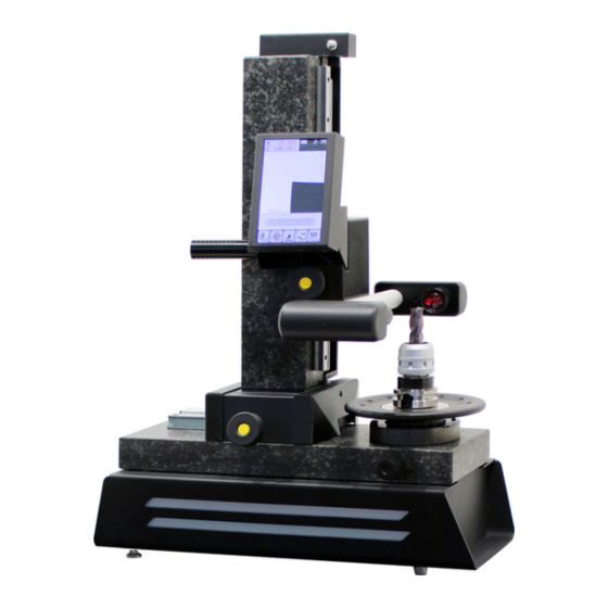
5. PREPARATION AND INSTALLATION ELBO CONTROLLI srl Preset E236+ 5.5.1 FRONT VIEW Counterweight spiral spring LCD Screen Touchscreen Handle for rapid axis Vision system movements illuminator Z axis fine feed knob C-MOS image sensor Rotating spindle X axis fine feed knob... -
Page 12: Rear View
5. PREPARATION AND INSTALLATION ELBO CONTROLLI srl Preset E236+ ( k ) ( l ) 5.5.2 REAR VIEW Z axis slideway Counterweight spiral spring Z axis optical scale Vision system illuminator C-MOS image sensor X axis slideway Rotating spindle X axis optical scale... -
Page 13: Operating Conditions
5. PREPARATION AND INSTALLATION ELBO CONTROLLI srl Preset E236+ 5.6 OPERATING CONDITIONS The E236+ Presetter is a precision instrument, it shall be positioned in a trouble-free site (free from dust and/or corrosive air substances, excessive vibrations, violent ranges of temperatures) safe from sunrays, direct illumination and far from windows and skylights. -
Page 14: Usb Port
5. PREPARATION AND INSTALLATION ELBO CONTROLLI srl Preset E236+ ý Connection Procedure • Connect the Presetter to the earthing terminal, using the yellow/green minimum sect. 1,5 mmq, fix it to the appropriate clamp. • Connect the eventual label printer s’Print-S to the serial port RS-232 (see para. 5.7.3) •... - Page 15 5. PREPARATION AND INSTALLATION ELBO CONTROLLI srl Preset E236+ The s’Print-S label printer must be connected directly to the serial RS-232 communication port of the presetter. E236 porta RS-232 Insert the telephonic type RJ11into the socket on the underside of the printer.
- Page 16 5. PREPARATION AND INSTALLATION ELBO CONTROLLI srl Preset E236+ Setting to edit: 19200 bps Setting to edit: RTS/CTS Setting to verify: CR disabled Setting to edit: Enable To darken the print set +1 o To check and if necessary, to restore the correct settings following the instructions that are printed from...
-
Page 17: Description Of Command
6. DESCRIPTION OF COMMAND ELBO CONTROLLI srl Preset E236+ 6. DESCRIPTION OF COMMAND 6.1 DISPLAY PANEL The LCD display panel is the point from which it is possible to activate all the functions of the instrument by acting directly on the "touch-screen". -
Page 18: Axis Movement
6. DESCRIPTION OF COMMAND ELBO CONTROLLI srl Preset E236+ 6.2 AXIS MOVEMENT The movements of the axes are manual and have two modes, fast and fine. The rapid movement is used to bring the tool within the visual field and to move away at the end of the measurement;... -
Page 19: The Spindle
6. DESCRIPTION OF COMMAND ELBO CONTROLLI srl Preset E236+ 6.3 THE SPINDLE The E236+ is equipped with an interchangeable rotating spindle system in which it is possible to insert different rotating spindles of a pre-selected shape and measure (ISO, BT, HSK, VDI…). -
Page 20: Basic Functions
6. DESCRIPTION OF COMMAND ELBO CONTROLLI srl Preset E236+ 6.4 BASIC FUNCTIONS 6.4.1 TURNING ON To turn on the instrument by inserting the 24Vcc power supply pin into the socket found on the rear panel; then insert the feeder plug into an electric socket (115-230Vac). -
Page 21: Turning Off
6. DESCRIPTION OF COMMAND ELBO CONTROLLI srl Preset E236+ 6.4.2 TURNING OFF To completely turn off the instrument, remove the power supply plug from the rear panel or the feeder from the electric socket. It’s also possible to use the stand-by function, however, it is worth knowing that in this mode power consumption is extremely reduced but not absent (ca. -
Page 22: Collimation
7. COLLIMATION ELBO CONTROLLI srl Preset E236+ 7. COLLIMATION 7.1 INTRODUCTION Collimation is the operation that detects the point in which you have to carry out the measurement. E236+ is equipped with an industrial vision system, which was exclusively designed for tool measurement/prerecording without contact. - Page 23 7. COLLIMATION ELBO CONTROLLI srl Preset E236+ Light beam Cutting edge The focusing control bars supply information about image sharpness in the measurement points that are specified in the figure; therefore, it’s possible to obtain different pieces of information (in the maximum value) for different tools or also for different cutting edges in the same tool.
-
Page 24: Collimation Mode
7. COLLIMATION ELBO CONTROLLI srl Preset E236+ SHOOTING LENS OPTIMAL FOCAL LENGTH FOCUSING MAXIMUM VALUE SPINDLE ROTATION AXIS As you can see, the residual inaccuracy value (S1, S2, S3, and S4) depends on the radius of the measured tool and approximately corresponds to 0.01 mm, for tools having a radius of 20 mm, while it is smaller than 0,001 mm. -
Page 25: Auto-Targeting Measurement
7. COLLIMATION ELBO CONTROLLI srl Preset E236+ Converts the fixed reticule mode, circular reticule and auto- targeting. Rotate the angle fixed reticule counterclockwise by increments of 1.00 degrees (enabled only with the displayed angle reticule). Angle setting to display with 0.01 degrees resolution (enabled only with the displayed angle reticule). -
Page 26: Measuring On The Fixed Reticule
7. COLLIMATION ELBO CONTROLLI srl Preset E236+ In the images, you can note the presence of small differences in the dimensions that are automatically detects in various points of the screen. This is due to the machining tolerances of illuminator and objective lens, as well as other factors of optical, electrical and mechanical type. -
Page 27: Measurement With Fixed Angular Reticle
7. COLLIMATION ELBO CONTROLLI srl Preset E236+ 7.3.3 MEASUREMENT WITH FIXED ANGULAR RETICLE With the angular reticule enabled, it’s possible to rotate on the left and on the right the displayed angle pressing the icons. The rotation will be carried out with 1.00 degrees increases/decreases. -
Page 28: Measurement With Fixed Circular Reticle
7. COLLIMATION ELBO CONTROLLI srl Preset E236+ 7.3.4 MEASUREMENT WITH FIXED CIRCULAR RETICLE Pressing again the icon, it’s possible to display the fixed circle reticule. It will be possible to switch the radius of the standard inserts from 0,4 mm to 2,0 mm, matching the tool profile with the circumference arcs on the reticule. -
Page 29: Optical Measurement
7. COLLIMATION ELBO CONTROLLI srl Preset E236+ If you observe the position of the focusing bars, you can recognize the active direction of collimation, indeed the bars move according to the measuring direction. 7.4.1 OPTICAL MEASUREMENT Despite the fact that E236+ can detect and measure the tool profile in any orientation, there are particular cases in which measurement cannot be performed automatically or with the assistance of electronic comparisons. -
Page 30: How To Use The Instrument
8. HOW TO USE THE INSTRUMENT ELBO CONTROLLI srl Preset E236+ 8. HOW TO USE THE INSTRUMENT 8.1 MACHINE ORIGIN SELECTION Before using the instrument to measure any tool, you have to set a correct starting reference: the origin. When switched on the instrument suggests the origin M0 as a default with the same refences and the same options radius/diameter, millimetre/inch, absolute/incremental enabled when the machine was switched off. -
Page 31: How To Select Radius / Diameter
8. HOW TO USE THE INSTRUMENT ELBO CONTROLLI srl Preset E236+ 8.2 HOW TO SELECT RADIUS / DIAMETER radius Select the “display settings” menu, by pressing the icon, then press alternatively the selection icon Radius/Diameter to see the dimension in X changing in both ways The dimension shown is the radius of the measured tool. -
Page 32: How To Select Absolute / Incremental
8. HOW TO USE THE INSTRUMENT ELBO CONTROLLI srl Preset E236+ The value shown is in inches; five decimal places are displayed inch At the top right of the screen, is indicated the unit of measure active. To exit the “display settings” menu press the icon. -
Page 33: Geometrical Calculus And Label Printing
8. HOW TO USE THE INSTRUMENT ELBO CONTROLLI srl Preset E236+ 8.5 GEOMETRICAL CALCULUS AND LABEL PRINTING By connecting the specific optional label printer s’Print-S, it is possible to transfer the measures of the tool and its geometry onto adhesive thermal paper, including a small image with the shape of the tool. - Page 34 8. HOW TO USE THE INSTRUMENT ELBO CONTROLLI srl Preset E236+ þ Attention: it is possible to use all the measurement modes available to store the value of X and Z to print, the only trickiness is to do it before the geometric calculus effect, otherwise the geometric drawing can’t coincide with the profile of the tool.
-
Page 35: System Settings
8. HOW TO USE THE INSTRUMENT ELBO CONTROLLI srl Preset E236+ When all necessary measurements have been carried out, press the icon to print the following label: Active machine origin X axis measurement Tool image Z axis measurement Radius Angle To exit the “print”... -
Page 36: Calibration Of The Vision System
8. HOW TO USE THE INSTRUMENT ELBO CONTROLLI srl Preset E236+ 8.7.1 CALIBRATION OF THE VISION SYSTEM CALIBRATION OF THE VISION SYSTEM The calibration allows adapting the real optical blow-up of the image to axes. In fact, the position on the screen is estimated in “pixel”, the image sensor uses 480x480, while the framed vision area is about 5x5... -
Page 37: Calibration Of The Touch Screen
8. HOW TO USE THE INSTRUMENT ELBO CONTROLLI srl Preset E236+ þ It’s advisable to add, in the positioning window move the axes in the same direction, for example from the bottom to the top for the Z-axis from the right to the left for the X-axis. - Page 38 8. HOW TO USE THE INSTRUMENT ELBO CONTROLLI srl Preset E236+ It serves to use a “pointed-pen” for the touchscreen, touch in sequence on the screen the points indicated: At the end it is possible to verify the outcome of the calibration by trying to touch the screen in different positions and in particular in the zone at the bottom of the LCD.
-
Page 39: Linear Compensation Of Axes Measurement
8. HOW TO USE THE INSTRUMENT ELBO CONTROLLI srl Preset E236+ For a new request to repeat the calibration procedure press , otherwise to exit without saving press 8.7.3 LINEAR COMPENSATION OF AXES MEASUREMENT Due to employment of temperatures that differ from 20°C, it may be necessary to correct the measurements detected by the Preset in order to restore the correct value. - Page 40 8. HOW TO USE THE INSTRUMENT ELBO CONTROLLI srl Preset E236+ Type in the actual dimension that has to be displayed , confirm it by pressing the axis It will calculate the compensation factor that is necessary to correct the display, then it will be stored and activated.
-
Page 41: How To Restore Standard Settings
8. HOW TO USE THE INSTRUMENT ELBO CONTROLLI srl Preset E236+ 8.8 HOW TO RESTORE STANDARD SETTINGS E236+ stores all settings (from display and axes origin settings to system settings: optical calibration and measurement compensation) in an EEPROM memory. All these data are saved in two different memory areas and completed by the CRC control to check their integrity. -
Page 42: Machine Origins
9. MACHINE ORIGINS ELBO CONTROLLI srl Preset E236+ 9. MACHINE ORIGINS 9.1 NC MACHINE ORIGINS In case of tool measurement options, there are no particular problems in the X-axis radial measurements, but a conventional reference point must be established for length (Z-axis) measurements. In fact, when a tool radius or diameter is measured, the zero point will always be located on the tool, the situation is quite different for length measurements. -
Page 43: Default Machine
9. MACHINE ORIGINS ELBO CONTROLLI srl Preset E236+ 9.2 DEFAULT MACHINE As described in paragraph 8.1, after having switched on the machine and acquired reference zero points for axes X and Z, the preset enables a fictitious machine source called “M0”. - Page 44 9. MACHINE ORIGINS ELBO CONTROLLI srl Preset E236+ Type and confirm pressing they icon The window that appears shows the options to create a new machine origin that the system will set to M1 that is the first one available in numerical order.
- Page 45 9. MACHINE ORIGINS ELBO CONTROLLI srl Preset E236+ E.g. Confirm the dimension with the icon The set dimensions are shown beside their respective icons. E236+ allows the acquisition of the machine origins whether in auto- collimation mode or through the use of the fixed reticule. As illustrated in the para.7.3, for a higher precision of the measure it’s advisable to memorize...
-
Page 46: Multifunction Machine Origin Configuration
9. MACHINE ORIGINS ELBO CONTROLLI srl Preset E236+ Press to exit the machine origins function and start to measure or press and repeat the previous procedure to create a new machine origin. As shown in the picture, beside the number (M1 ÷ M9) the system will assign to each origin the name “no name”. -
Page 47: Ac Tivation Of Anc Machine Origin
9. MACHINE ORIGINS ELBO CONTROLLI srl Preset E236+ When the desired axes configuration is settled, press the icon to return to the base settings or to continue with offset measurement procedure, as described in the previous paragraph. þ Attention: the offset measurement, by pressing , icons, must be carried out after having settled the counting direction and the axes assignment. -
Page 48: Edit Or Delete Anc Machine Origin
9. MACHINE ORIGINS ELBO CONTROLLI srl Preset E236+ Press here! Press the icon to confirm the selected origin. The screen will return to the main page; the dimensions displayed will be updated and referred to the requested machine that is shown in the top right of the screen. - Page 49 9. MACHINE ORIGINS ELBO CONTROLLI srl Preset E236+ To cancel the machine origin, press the icon , the system will ask you to confirm the operation: Selecting the machine origin will be deleted, selecting it will go back to the previous window.
-
Page 50: Toolset
10. TOOLSET ELBO CONTROLLI srl Preset E236+ 10. TOOLSET 10.1 INTRODUCTION E236+ has the possibility to store and manage the measurement carried out in nine different lists: the "toolset” (S1 ÷ S9); each of which must be associated with a machine origin and can contain a maximum of 99 tools. - Page 51 10. TOOLSET ELBO CONTROLLI srl Preset E236+ Machine origin number and setting Toolset number Tool no.1 to 0 While in the lower part of the screen the first record will appear of the number of tools defined for the Set: For each tool it’s possible to be memorized: the letter “T“...
- Page 52 10. TOOLSET ELBO CONTROLLI srl Preset E236+ Pressing the icon , the system will analyse the profile of the tool to search, if it is detected, the radius will be drawn on the screen and the measure will be inserted in the proper field:...
-
Page 53: Edit A Toolset
10. TOOLSET ELBO CONTROLLI srl Preset E236+ 10.3 EDIT A TOOLSET It's possible to access the toolset to add, remove, measure the tools or print the label of it. From the main menu, press the icon in order to open the memorized Toolset list. -
Page 54: Delete Toolset And Tools
10. TOOLSET ELBO CONTROLLI srl Preset E236+ If we try to insert an existing tool number in the Set this will be aborted by the system with the message: It’s also possible to directly insert/modify the measurements with the numerical icon board by pressing the stored values. -
Page 55: Label Printing
10. TOOLSET ELBO CONTROLLI srl Preset E236+ 10.5 LABEL PRINTING If your presetter is connected to a mini label printer s’Print-S, it is possible to transfer measurements on to labels stored in the Tool Set. From the main menu, press the icon to open the list of Toolsets stored in the memory. -
Page 56: Td236+ Software
11. TD236+ SOFTWARE ELBO CONTROLLI srl Preset E236+ 11 TD236+ Software The TD236+ software, installable on a PC with a Microsoft Windows operating system is found on the ® CD enclosed with the machine together with the user’s current maintenance and usage manual. -
Page 57: Software Registration
11. TD236+ SOFTWARE ELBO CONTROLLI srl Preset E236+ Connect the USB port of the presetter with the USB port of the PC in the one which was installed in TD236+, at the connecting of the cable, the PC will automatically proceed to install on the driver the necessary functions. -
Page 58: Use Of The Software
11. TD236+ SOFTWARE ELBO CONTROLLI srl Preset E236+ An alphanumeric registration code of 14 characters will be sent to the specified e-mail address; copy it and insert it in the appropriate space respecting the upper case and lower-case letters, then press the icon Not until the registration code is available is it possible to proceed to unlimited use of the software pressing at each request. - Page 59 11. TD236+ SOFTWARE ELBO CONTROLLI srl Preset E236+ In whichever moment it is possible to import/export the data by pressing the icon: EXPORT DATA IMPORT DATA The selection of a machine will show the configuration to be associated: Here it is possible to assign a name to the machine, select the format of the post-processor from those available, define the maximum number of tools acceptable on the corrector’s chart of the numeric control...
- Page 60 11. TD236+ SOFTWARE ELBO CONTROLLI srl Preset E236+ At the same way selecting a tool chart will show the contents in a grill form: Control box for including the tools in the file of the corrector File corrector in the...
-
Page 61: Configuration And Restoring Data
11. TD236+ SOFTWARE ELBO CONTROLLI srl Preset E236+ Moving the tool chart on to another machine Through this function it is possible to change the machine of the tool chart selected. The tool correction values will be edited in accordance with the difference between the machine of origin and that of destination. - Page 62 11. TD236+ SOFTWARE ELBO CONTROLLI srl Preset E236+ To restore the data, access the configuration menu: in the entry “Restore data” there is listed the copies available to restore, from the oldest to the most recent (year, month, day). To select the copy of the data requested and to confirm the operation: The data therefore can be edited, printed, “post-process”...
-
Page 63: Updating Bios
Registering the TD236+ software, will automatically notify you of the availability of a new update for their Preset and supply a link to download it. Otherwise, it will be necessary to identify the adapted file in function to the model and serial number of the presetter, navigating the Download area of the Elbo Controlli site. - Page 64 11. TD236+ SOFTWARE ELBO CONTROLLI srl Preset E236+ It will initialize the transmission of the file from the PC to the presetter; wait until the file transmission is complete. At the same time, also on the screen of the E236+ you can follow the flow of the data from the PC to the presetter.
- Page 65 11. TD236+ SOFTWARE ELBO CONTROLLI srl Preset E236+ Erasing the pre-existing BIOS. ATTENTION: The switching off of the instrument, even accidentally, in this phase will render it unusable Writing the new BIOS ATTENZION: The switching off of the instrument, even...
-
Page 66: Maintenance
12. MAINTENANCE ELBO CONTROLLI srl Preset E236+ 12. MAINTENANCE 12.1 ORDINARY MAINTENANCE The presetter does not normally need scheduled maintenance: However, should it be necessary, carry out the following simple interventions. 12.1.1 LUBRICATION OF GAUGES, ADAPTORS AND SPINDLES To maintain the aforesaid basic parts of the presetter perfectly efficient and ensure their precision, you have to clean and lubricate them any time they are replaced and then store them in a dry place. -
Page 67: Troubleshooting
13. TROUBLESHOOTING ELBO CONTROLLI srl Preset E236+ 13. TROUBLESHOOTING 13.1 INTRODUCTION This chapter is a guide to solve the most common problems that can occur while using the presetter. Each problem that can be detected is mentioned together with a series of checks that have to be carried out and the possible corrective actions that can solve them. -
Page 68: Problem
13. TROUBLESHOOTING ELBO CONTROLLI srl Preset E236+ PROBLEM: Irregular behaviour during the use of the device. CAUSE: Due to power supply loss while saving the data, the content of the memory can be altered origins, settings). SOLUTION: restore the standard settings (see par. 8.8). -
Page 69: Disposal
14. DISPOSAL ELBO CONTROLLI srl Preset E236+ 14. DISPOSAL Information obligations to the users DISPOSAL OF WASTE MATERIALS INFORMATION FOR PROFESSIONAL USERS - VALID IN EUROPEAN COMMUNITY ONLY - As per the 2012/19/EU Directives, concerning the reduction in the use of hazardous substances in electrical and electronic apparatuses, as well as the disposal of waste materials. - Page 71 The information and specifications contained in this manual are subject to change without prior notice. No part of this manual may be reproduced, in any way or form, without the written consent of ELBO CONTROLLI s.r.l. Via S Giorgio, 21 20821 Meda (MB) ITALIA +39 0362 342745 info@elbocontrolli.it...
Need help?
Do you have a question about the E236+ and is the answer not in the manual?
Questions and answers