
Subscribe to Our Youtube Channel
Related Manuals for Assa Abloy Securitron AQE Series

Summary of Contents for Assa Abloy Securitron AQE Series
- Page 1 AQE-Series Multi-port Power Over Ethernet Midspan Injector Installation Manual 500-33600, Rev. A...
-
Page 2: Table Of Contents
Table of Contents Notes and Warnings ........iii Symbol Definitions . -
Page 3: Notes And Warnings
Notes and Warnings Symbol Definitions Regulatory Information The following symbols are used in the Warnings section The equipment discussed within this manual has been below: tested to the following standards: This symbol alerts the installer of shock hazards • EN60950 EN55022 CLASS A EN55024 within the enclosure. -
Page 4: Introduction
Introduction Product Description The illustration below shows the model numbering convention of the AQE series using an example model The AQE series of multi-port Power over Ethernet (PoE) number. AQE indicates the model series. The number “500” midspan injectors are designed to provide power to indicates a total of 500 Watts nominal output power available. -
Page 5: Section 1 - Installation
Section 1 – Installation The following pages cover the installation of the AQE-series rack-mountable PoE power supplies. 1.1 Mounting the AQE Rack Mount Supply into a Standard 19" Rack Use the following procedure when mounting an AQE-series NOTE: Rails or other appropriate support for heavy supply into a standard Electronics Industry Alliance (EIA) enclosures shall be used. -
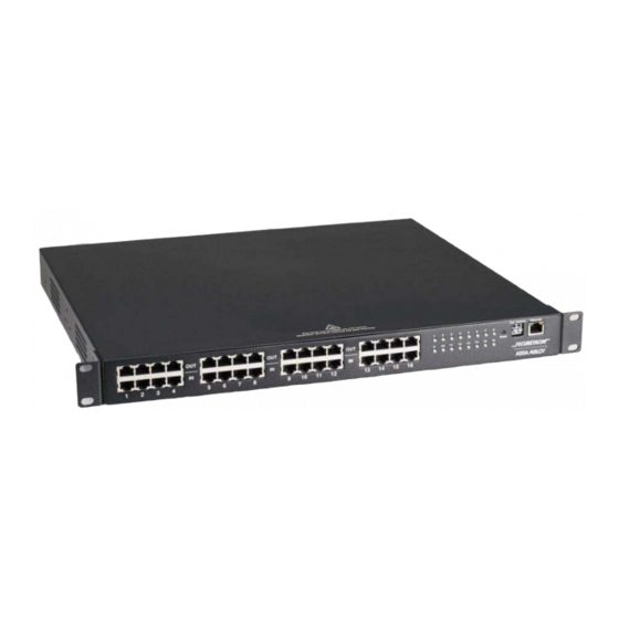
Page 6: Aqe Rackmount Power Supply Overview
1.2 AQE Rackmount Power Supply Overview Figure 2: AQE Front View – No user serviceable parts inside refer servicing to qualified service personnel Aucune pièce interne ne peut être réparer Demandez l’assistance d’un technicien qualifié External DC On / Off AC Power Figure 3: AQE Rear View 500-33600, Rev. - Page 7 The following are basic descriptions. Refer to the appropriate section for more detailed information. PoE Input / Output (IN / OUT) AC Line Input (AC Power) There sixteen RJ45 jack pairs (top and bottom pair) labeled This is the connector for the AC line cord. sequentially.
-
Page 8: Section 2 - Initial Configuration
Section 2 – Initial Configuration The AQE Power Supply Control Center management software allows users to configure, as well as monitor and control each output port of the AQE series midspan injector. It is embedded and web browser based and does not require the installation of any dedicated software on the user's PC. -
Page 9: Configuring The Tcp/Ip Settings
Figure 6: AQE Power Supply Control Center opening (HOME) page 2.3 Configuring the TCP/IP Settings Net Mask Should typically be set to 255.255.255.0 In the orange menu bar at the top of the browser screen, click the "Configure" link. Figure 7 shows the Configure page. MAC address The MAC Address is factory set and is not programmable At the top left of the Configure page is the “TCP/IP Setting”... -
Page 10: Configuring The Administration Settings
Enable DHCP "Submit" button - a popup message will confirm a successful Normally, this option is left unchecked, however in some password change. When you leave the configure page, the cases you may want to allow the network to assign an IP AQE will ask you to re-log in. -
Page 11: Configuring The Email Settings
the settings. These settings will take effect after a reboot of Sender's Email the AQE. This is the email address which the AQE will use to send emails. The "Security Name" section of the SNMP Setting block allows you to grant only specified computers (by IP Sender Email Password address) SNMP v1 and v2 access. -
Page 12: The Programming Page
Figure 8: Bottom half of the AQE Power Supply Control Center Configure page 2.7 The Programming Page To enable upper and lower limit checking, CHECK the box next to “Voltage & Current Limit Setting” at the top of the Figure 9 shows the Programming page of the AQE Power screen. -
Page 13: Section 3 - Using The Aqe
Section 3 – Using the AQE 3.1 Viewing System Parameters on the AQE Home Page Auto-refresh CLICK the "Enable" button to turn on auto-refresh for the The Home Page is shown in Figure 10. To access the home page. Auto Refresh automatically reloads the page Home Page, CLICK "Home"... - Page 14 Priority Class This column allows users to set a priority for each port. This column displays the power class of each port. The For each port there is a corresponding priority drop-down “power class” information is provided by the connected list where a priority between 0 and 15 can be selected Powered Device (such as a PoE compatible IP camera) (where “0”...
-
Page 15: The Tools Page
3.2 The Tools page Rebooting the AQE The "Reboot" section is on the top right of the Tools page (See Upgrading Firmware Figure 11). To reboot the AQE, CLICK the "Submit" button. The Upgrade Firmware section is at the top left of the Once the "Confirm Reboot"... -
Page 16: Appendix 1 - Software Agreement And Warranty Statement
Appendix 1 – Software License Agreement and Warranty Statement and control at one (1) facility of Recipient. Recipient NOTICE: PLEASE READ THIS DOCUMENT CAREFULLY. may install the Software and may access the Software by concurrent users over a network connection in This Software License Agreement ("AGREEMENT") defines and governs use of HANCHETT ENTRY accordance with the Documentation. - Page 17 by means of translating the object code, which may be (j) Software License Compliance Audit. HANCHETT provided by HANCHETT ENTRY SYSTEMS, INC. under this ENTRY SYSTEMS, INC. may audit Recipient's use of the Agreement, (including object code in ROM memory chips Software on thirty (30) days' advanced written notice.
- Page 18 (iii) use of the Software in combination with hardware QUALITY, OR FITNESS FOR ANY PARTICULAR PURPOSE. or software or Third Party Information not provided (c) HANCHETT ENTRY SYSTEMS, INC. PROVIDES by HANCHETT ENTRY SYSTEMS, INC.: (A) that is specifically forbidden by the Documentation; or (B) that NO TECHNICAL SUPPORT OR REMEDIES FOR THE SOFTWARE.
- Page 19 (e) Choice of Law & Jurisdiction. This AGREEMENT shall (n) Notice to U.S. Government End Users. The be governed solely by the internal laws of the State of development of the Software has been exclusively at Arizona, without reference to such State's principles of the private expense of HANCHETT ENTRY SYSTEMS, conflicts of law.
- Page 20 Securitron 10027 South 51st Street, Suite 102 Phoneix, AZ 85044 Phone: (623) 582-4626 Fax: (623) 582-4641 securitron.com © 2014, Hanchett Entry Systems, Inc., an ASSA ABLOY Group Company. 500-33600, Rev. A...
Need help?
Do you have a question about the Securitron AQE Series and is the answer not in the manual?
Questions and answers