
Subscribe to Our Youtube Channel
Related Manuals for Holaday Industries HI-3604

Summary of Contents for Holaday Industries HI-3604
- Page 1 HI-3604 ELF Survey Meter User's Manual © Copyright 1992 Holaday Ind. Inc. Manual #600043B 6/97 $12.50...
- Page 3 Revision Record Manual # 600043 HI-3604 Survey Meter Revision Description Date Release 8/92 New LCD 12/92 Added CE Label 6/97...
-
Page 5: Table Of Contents
TABLE OF CONTENTS DESCRIPTION ......SPECIFICATIONS ......4 OPERATION . - Page 7 LIMITED WARRANTY HOLADAY INDUSTRIES, INC. WARRANTS EACH MODEL HI-3604 ELF SURVEY METER TO BE FREE FROM DEFECTS IN MATERIAL AND WORKMANSHIP FOR A PERIOD OF ONE YEAR FROM DATE OF SHIPMENT TO THE PURCHASER. THIS WARRANTY EXTENDS TO THE ORIGINAL...
-
Page 9: Description
(Model HI-3616) which is available as an option. The HI-3604 finds applications in research and environmental field studies where knowledge of the strength of power frequency fields is required. - Page 10 HI-3604 will yield consistent measures of the RMS field strengths.
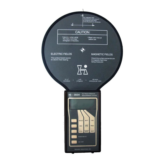
- Page 11 HI-3604 Manual Page -- 3 Figure 1-1 HI-3604 ELF Field Strength Measurement System...
- Page 12 Page -- 4 HI-3604 Manual...
-
Page 13: Specifications
HI-3604 Manual Page -- 5 SPECIFICATIONS Sensors: Concentric plate displacement current electric field sensors 6.5 inch (16.5 cm) diameter 400 turn electrically shielded magnetic field sensing coil Switch selectable between electric magnetic fields Sensitivity: Electric fields, 1 V/m - 199 kV/m Magnetic fields, 0.1 mG - 20 G... - Page 14 Page -- 6 HI-3604 Manual Power: Two (2) nine-volt alkaline batteries (NEDA 1604A, Duracell MN1604, or equal) Output: Liquid crystal display; preamplifier output via p h o n o j a c k ( a n a l o g...
- Page 15 Page -- 7 HI-3604 Electric Field Response Figure 2-2 The HI-3604 Power Frequency Field Strength Meter package includes the Readout-Sensor assembly, batteries, a fitted carrying case and a user manual. Instrument accuracy is derived from a field calibration using a...
- Page 16 Page -- 8 HI-3604 Manual The HI-3604 can be user programmed to indicate in either units of milligauss/gauss, milliamperes/amperes per meter, or nano/micro teslas. Refer to section 3.0 OPERATION for further details. The HI-3604 indicates magnetic field flux density in units of millgauss (mG) and gauss (G).
- Page 17 HI-3604 Manual Page -- 9 module. This signal is available from the phone jack located at the bottom of the instrument.Connection of an oscilloscope to this jack will allow observation of the preamplifier output.
- Page 18 Page -- 10 HI-3604 Manual...
-
Page 19: Operation
Use care in handling the HI-3604 to avoid damaging the sensor by striking it against objects or applying excessive force to the sensor paddle. - Page 20 Page -- 12 HI-3604 Manual Figure 3-1 HI-3604 ELF Survey Meter...
-
Page 21: Digital Display
(F- 2). The display response setting is stored in the non-volatile memory of the HI-3604 and if the setting is changed, the new setting will be saved and will become the default condition. For... -
Page 22: Keypad Inputs
ON/OFF - Pressing the ON/OFF keypad turns the instrument on; pressing the ON/OFF keypad again turns the meter off. As there is no automatic turn off on the HI-3604, turn the instrument off when not in use or between readings. No warm up is required before using the instrument. - Page 23 SCALE - The SCALE keypad changes the fixed ranges or scales of the instrument. When turned on, the HI-3604 is in the AUTO RANGE mode. The unit determines the correct range within the current mode (E or H field) according to the detected field level.
- Page 24 Page -- 16 HI-3604 Manual To return to the AUTO RANGE mode, press and hold the SCALE keypad until the AUTO indication is shown in the upper left area of the LCD. MAX - While using the instrument for field measurements, the processor is continually saving the highest indicated reading.
- Page 25 The instrument will normally be received from the factory with the display response filter set at F-2. The display response setting is stored in the non-volatile memory of the HI-3604 and if the setting is changed, the new setting will be saved and will become the default condition.
- Page 26 Page -- 18 HI-3604 Manual one second followed by the stored value. Immediately upon releasing the key, a new value may be logged by again pressing the LOG pad. Up to 112 values can be stored in this memory. When the memory is filled, successive operations of the LOG key will store the most current reading in memory location 112.
-
Page 27: Power Frequency Fields
POWER FREQUENCY FIELDS The HI-3604 finds application in numerous circumstances involving 60-Hz fields. A prime example of the HI-3604's utility is evaluation of electric and magnetic fields in the vicinity of electric power lines. In this case, the electromagnetic field environment surrounding a typical power transmission line can be visualized through Figure 4-1. - Page 28 Page -- 20 HI-3604 Manual Electric and magnetic fields produced by the power line originate because of the voltages impressed on the conductors and the magnitude of current (electricity) flowing through the conductors. Figure 6 depicts the approximate spatial orientation of these fields;...
- Page 29 HI-3604 Manual Page -- 21 oriented directly beneath the conductors but at extended lateral distances from the line, there can be some horizontal component to the field. Thus, in measurements of electric fields near power lines, it may be important to explore different polarization components of the field to assess the resultant electric fields at points above the earth.
- Page 30 Page -- 22 HI-3604 Manual...
-
Page 31: Example Applications
The operator should remain approximately one to two times their height away from the HI-3604 and observe the readings via the use of the HI-3616 Fiber Optic Remote Control. The instrument is supported with the digital readout facing upward;... - Page 32 Induced currents represent one potential dosimetric measure of electric field exposure. Measurement of the electric field strength beneath power lines may also be accomplished by laying the HI-3604 on its back...
- Page 33 In either case, with the instrument elevated on a tripod or laying on the ground, the HI-3604 should be oriented so that the long axis of the body of the instrument is parallel to the conductors of the power line.
-
Page 34: Waveform Measurements
Waveform Measurements A useful feature of the HI-3604 is the ability to display waveform information about electric or magnetic fields being sensed. The waveform display output is a 1/8 inch phone jack located on the bottom of the instrument case. - Page 35 HI-3604 Manual Page -- 27 longer part of the waveform trace in Figure 5-6 is related to the time it takes for the beam to travel from the top of the screen to the bottom; the very short transition in the waveform is the time it takes for the beam to return to the top of the screen after reaching the bottom.
- Page 36 (sine wave) produced by an incandescent light bulb obtained by use of an oscilloscope connected to the analog output jack on the HI-3604. Figure 5-4 Waveform of magnetic field produced by an incandescent light bulb operated by a light...
- Page 37 HI-3604 Manual Page -- 29 Figure 5-5 Waveform of current supplied by a light dimmer. Figure 5-6 Waveform of magnetic field produced by the vertical deflection circuit in a VDT obtained by monitoring the output from the analog output jack with an oscilloscope.
-
Page 38: Frequency Measurements
To perform this measurement, a portable digital multimeter (DVM) capable of measuring frequency maybe used with the HI-3604 to, for example, determine the vertical refresh rate on a VDT. To perform this measurement, an analog signal sufficient to drive some frequency counters may require that the... -
Page 39: Maintenance
Phillips flat-head screws and the nuts and lockwashers (on the two fiber optic connectors) on the bottom end plate of the HI-3604 readout module. The batteries are held in place by the end plate and will slide out easily when the plate is removed. - Page 40 Page -- 32 HI-3604 Manual...
-
Page 41: Using The Hi-3616 Fiber Optic Remote Control
(yellow to yellow; white to white). The HI-3616 is able to control all operations of the HI-3604 from its control panel in addition to displaying the measured field values. Section 6.0 provides instructions on replacement of batteries for both the HI-3604 and the HI-3616. - Page 42 HI-3604 Manual of the HI-3616 no longer responds; replace both batteries. The data link between the HI-3604 and the HI-3616 is a plastic fiber cable. While the fiber optic cable is generally very durable, avoid sharp bends in the cable and avoid placing the cable under tension (do not pull on it).
- Page 43 HI-3604 Manual Page -- 35 -NOTES-...
- Page 44 Page -- 36 HI-3604 Manual -NOTES-...
Need help?
Do you have a question about the HI-3604 and is the answer not in the manual?
Questions and answers