
Related Manuals for Daikin EWLD120MBYNN


Summary of Contents for Daikin EWLD120MBYNN
- Page 1 OPERATION MANUAL Condenserless water-cooled water chillers EWLD120MBYNN EWLD170MBYNN EWLD240MBYNN EWLD260MBYNN EWLD340MBYNN EWLD400MBYNN EWLD480MBYNN EWLD500MBYNN EWLD540MBYNN...
- Page 2 The EWLD Type semi-hermetic single screw units can be combined with Daikin fan coil units or air handling units 1x ZHA7MSGUYE for air conditioning purposes. They can also be used for supplying...
-
Page 3: Electrical Specifications
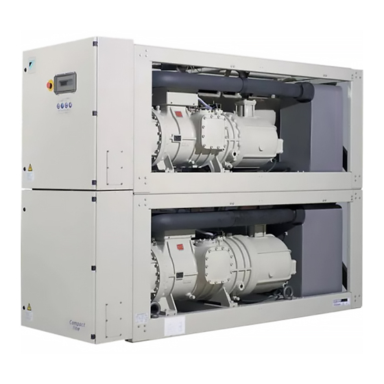
General EWLD Dimensions HxWxD 2000x2672x930 (mm) Weight 2684 2770 2856 • machine weight (kg) 2738 2831 2924 • operation weight (kg) Connections • chilled water inlet and 2x 3" (88.9 mm OD) (inch) outlet • remote condenser connection 2x 2"1/8 2"1/8+2"5/8 2x 2"5/8 discharge... - Page 4 ESCRIPTION The EWLD water-cooled water chillers are available in 9 standard sizes. Figure - Main components Compressor Digital display controller Evaporator Emergency stop Switchbox Power supply intake Compressor switchbox Field wiring intake Charge valve Holes for lifting Safety valve Transportbeam High pressure switch Ballvalve liquid pipe Drier...
-
Page 5: Function Of The Main Components
Function of the main components R10T Y11S Y21S S1PH S14PH S2PH S15PH Y15S Y16S Y26S EWLD120~260 EWLD340~540 Figure - Functional diagram Evaporator Strainer only for EWLD120~170 Water out Sightglass only for EWLD240~260, EWLD400~540 Water in Suction stop valve (option) only for EWLD340 Drier Electronic expansion valve only for EWLD340~400... -
Page 6: Safety Devices
Safety devices Internal wiring - Parts table The unit is equipped with three kinds of safety devices: Refer to the internal wiring diagram supplied with the unit. The abbreviations used are listed below: General safety devices A1,A2..** ..Current transfo / A-meter circuit 1, circuit 2 General safety devices shut down all circuits and stop the whole A1P...... -
Page 7: Before Operation
L1,L2,L3....Main supply terminals EFORE OPERATION M1C,M2C....Compressor motor circuit 1, circuit 2 M1S,M2S ....Stepless capacity control for compressor Checks before initial start-up circuit 1, circuit 2 M11F~M16F ..Fan motor circuit 1 Make sure that the circuit breaker on the power supply M21F~M26F .. -
Page 8: Water Supply
Water supply PERATION Fill the water piping, taking into account the minimum water volume The EWLD120~540 units are equipped with a digital controller required by the unit. Refer to the "installation manual". offering a user-friendly way to set up, use and maintain the unit. Make sure that the water is of the quality as mentioned in the This part of the manual has a task-oriented, modular structure. - Page 9 Switching the unit on key, to enter the user password menu. key, to enter the DICN menu, also referred to as network Press the J key on the controller. menu (optional). Depending on the setting of the remote ON/OFF control key, has no effect on EWLD units parameter (refer to the service manual), the following conditions may occur.
-
Page 10: Adjusting The Temperature Setpoint
Press the h key to enter the next screen of the readout menu. Consulting actual operational information (Only for EWLD340~540.) screen of the readout menu provides Enter the readout menu. Refer to the chapter "How to enter a information concerning the pressures of the second circuit. menu"... - Page 11 Advanced features of the digital controller To adjust other setpoints, repeat from instruction 2 onwards. This chapter gives an overview and a brief functional description of NOTE When a setpoint on a unit in a DICN system is set, this the screens provided by the different menus.
-
Page 12: Timers Menu
Timers menu To define the lead-lag mode of both circuits (only for EWLD340~540). To check the actual value of the general software timers. To define the capacity limitations (first screen). To check the actual value of the compressor timer. (first screen) define capacity limitations... -
Page 13: History Menu
To check which were the total amount of To check the status of the power relays running hours of the compressors at the of circuit 2. moment of shutdown. To check which was the capacity of each circuit at the moment of shutdown. - Page 14 Tasks of the user settings menu Defining the lead-lag mode (only for EWLD340~540) Entering the user settings menu The lead/lag mode determines which of both circuits starts up first in case of a capacity demand. The user settings menu is protected by the user password, a 4-digit The lead-lag parameters are: number between Enter the...
- Page 15 Each day of the week can be appointed to a group. The actions defined Defining the display settings in a group will be executed in each day belonging to that group. : used to define to which screens of the usersettings menu allows group each day of the week belongs ( / the user to define the choice of language, time and date.
- Page 16 Tasks of the timers menu NOTE Put a unit to when servicing the machine. In this case it is possible to switch ON or Checking the actual value of the software timers OFF this unit without switching ON or OFF the other units of the network.
- Page 17 Tasks of the safeties menu Tasks of the input/output menu Listing activated safeties and checking the unit status Checking the status of the inputs and outputs If the alarm buzzer is activated and the user presses the p key, the The input/output menu provides a means of checking the status of controller automatically enters the safeties menu.
-
Page 18: Changing The User Password
The changeable analog inputs are: When a safety device was activated, stop the unit and find out why the safety device was activated before resetting it. Under no circum- : indicates the status of the analog input stances safety devices may be bridged or changed to a value other : indicates the status of the analog input than the factory setting. - Page 19 Symptom 3: The unit does not start and the ON LED does not light up Symptom 5.5: Discharge thermal protector is activated OSSIBLE CAUSES ORRECTIVE ACTION OSSIBLE CAUSES ORRECTIVE ACTION Unit is working outside the operation Check the operation condition of the All circuits are in failure mode.
-
Page 20: Maintenance Activities
Symptom 10: The message shows AINTENANCE In order to ensure optimal availability of the unit, a number of checks OSSIBLE CAUSES ORRECTIVE ACTION and inspections on the unit and the field wiring have to be carried out A unit can not be found by the DICN Make sure all units in the DICN at regular intervals. - Page 21 NNEX NNEX Thermostat parameters Floating setpoint working The diagram and table below show the default value and the upper Inlet water temperature control/outlet water temperature and lower limits of the floating setpoint parameters on the evaporator. control Max, value The figure below shows the thermostat diagram. 5°C Fast load up Slow load up...
- Page 22 NNEX NNEX Schedule timer example Free cooling working Free cooling on ambient temperature MARCH free cooling state To come to the schedule above following settings have to be made: ambient temperature °C Free cooling default minimum maximum –30 (°C) (°C) Free cooling on difference between inlet water evaporator temperature and ambient temperature All days assigned to the same group will work according to the set-...
-
Page 23: Software Structure
NNEX OFTWARE STRUCTURE only for EWLD340~540 EWLD120~540MBYNN Operation manual Condenserless water-cooled water chillers 4PW22687-1... - Page 24 Zandvoordestraat 300, B-8400 Oostende, Belgium 4PW22687-1...
Need help?
Do you have a question about the EWLD120MBYNN and is the answer not in the manual?
Questions and answers