Table of Contents
Advertisement
Quick Links
Advertisement
Table of Contents

Related Manuals for GREMSY MIO


Summary of Contents for GREMSY MIO
-
Page 2: Revision History
REVISION HISTORY REVISION DATE DESCRIPTION User Manual April 16, 2021 LEGEND Notes are used to highlight special operating conditions or steps of a procedure. NOTE Warnings are used to highlight procedures which, if not strictly observed, may result in personal injury or loss of life. WARNING Tips. -
Page 3: Table Of Contents
MTX HUB CONNECTORS & PINOUTS Tilt Connectors & Pinouts What’s In The Box Hyper Quick Release Mounting Hyper Quick Release Connect Disconnect Powering Up The MIO Step 1 Step 2 Step 3 Status LED Indicator Operation Modes MIO Has 2 Operation Modes MIO Supports... - Page 4 Working Operation Swithing Between Modes INSTALLING SOFWARE Steps To Connect BALANCING Mounting The Camera Tilt Axis Front-Back Balance Tilt Axis Vertical Balance Roll Axis Balance Pan Axis balance SOFTWARE - TUNING Stiffness Tuning General Method Step 01 - Tilt Stiffness Step 02 - Roll Stiffness Step 03 - Pan Stiffness Filter...
- Page 5 Follow Mode Settings Speed Smooth Window Tilt Lock Rotation Limit Up Limit Down Limit Window IMU SENSOR Gypro Calibration Accelerometter Calibration REMOTE CONTROL SBUS/PPM Settings Receiver Connection Channel Setting UPGRADING FIRMWARE How To Upgrade TROUBLESHOOTING...
-
Page 6: Getting Started
GETTING STARTED... -
Page 7: Introduction
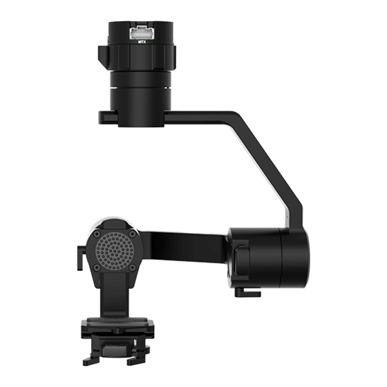
GETTING STARTED INTRODUCTION MIO is an ultra lightweight 3-axis gimbal that is specially designed for a wide variety of small cameras, features Hyper quick release with integrated HDMI, a variety of I/O interfaces and ability to start up in 2 seconds. -
Page 8: Features
I/O. UNIVERSAL Ability to adjust balancing in 3 axis allows MIO to mount a wide range of cameras such as FLIR DUO PRO R, FLIR VUE PRO R, SONY QX30, SONY UMC-R10C... View More Cameras >>... -
Page 9: High Performance Gimbal Controller
GETTING STARTED HIGH PERFORMANCE Advanced gimbal controller designed and GIMBAL CONTROLLER made by Gremsy based on a 32 bit high performance ARM microprocessor providing fast response and accurate calculation. Sensor data and motors correction are updated as fast as 2000 times per second to enable incredibly smooth footage. - Page 10 GETTING STARTED SPECIFICATIONS Product Name System Type 3-Axis Digital Gyro-Stabilized Weight 0.53 lbs / 240 g Maximum Payload 0.88 lbs / 400 g Construction All Aluminum Input Voltage UBEC 14 – 52V Input Voltage Gimbal 12V / 5A Working Current Static Current 400mA @12V Dynamic Current 800mA @12V Locked Motor Current Max 3.5A @12V...
-
Page 11: Mio I/O Connectors
GETTING STARTED MIO I/O CONNECTORS HYPER QUICK RELEASE POWER: 14V-52V input range. CONNECTORS & PINOUTS Connector type: JST SM02B-SFKH-TF USB: to interface with computer or Connector type: Micro USB type B HDMI: to output video from the camera Connector type: HDMI micro... -
Page 12: Mtx Hub Connectors & Pinouts
GETTING STARTED MTX: Multiplex port that combines AUX , COM1/COM2/COM4 ,CAN, SBUS,PPM into a single connector. In order to access these interfaces easily, it is necessary to use MTX hub . Connector type: Molex 20pin 501571 MTX HUB CONNECTORS & COM1/CAN: COM1 is a serial protocol PINOUTS (UART) port which is used to interface with... - Page 13 GETTING STARTED SBUS/PPM: to interface with SBUS/PPM receiver. This port is internally connected to SBUS/PPM port on the gimbal controller. Connector type: 3 pin, 2.54mm pitch AUX: there are optional signals S1, S2, S3, S4, S5, S6, S7, S8 (0.3A max) for users to connect to other devices such as AV signal or camera trigger, ..This port is internally connected to AUX port on the tilt axis.
-
Page 14: Tilt Connectors & Pinouts
GETTING STARTED TILT CONNECTORS & AUX: Provide 12V output (1A max) to PINOUTS power camera and accessories and optional signals S1, S2, S3, S4, S5, S6, S7, S8 (0.3A max) for users to connect to other devices such as AV signal or camera trigger, ..This port is internally connected to AUX port on the hyper quick release. -
Page 15: What's In The Box
GETTING STARTED WHAT’S IN THE BOX 1. MIO GIMBAL 2. MIO ACCESSORIES A. Micro USB Cable G. Pixhawk Cable B. Power Cable H. DJI Cable C. AUX Cable (QR) I. SBUS/PPM Cable D. AUX Cable (Tilt) J. Allen Key 1.5 E. -
Page 16: Hyper Quick Release
GETTING STARTED HYPER QUICK RELEASE MOUNTING HYPER QUICK Using 4xM2.5 to mount the top part onto the frame or damping isolator. RELEASE Pay attention to the arrow on the hyper quick release which indicates the home position or forward position of the gimbal. Connect the power cable to the Hyper Quick Release. -
Page 17: Connect
STEP 3: Rotate the ring clockwise until the mark on the ring aligned with the locked icon. DISCONNECT STEP 1: Rotate the ring counterclockwise. STEP 2: When the mark on the ring aligned with the unlock icon, the MIO can be detached from the top part of the Hyper Quick Release. USER MANUAL... -
Page 18: Powering Up The Mio
After connecting to the power supply, the gimbal will perform a series of alignments, self tests, which last about 2 seconds and the status of the gimbal THE MIO will be indicated by the Status LED color. During this time, don’t touch the gimbal or camera. -
Page 19: Status Led Indicator
GETTING STARTED STATUS LED INDICATOR STATE LED STATUS DESCRIPTION Blink Low Battery Solid System Error (Motor or IMU) Blink Calibrating Solid System Boot Blink System Ready Blink Lock Mode Solid Follow Mode Blink Remote with Lock Mode Solid Remote with Follow Mode USER MANUAL... -
Page 20: Operation Modes
GETTING STARTED OPERATION MODES MIO HAS 2 OPERATION LOCK MODE: is a stabilization mode where the camera maintains orientation MODES independently of the rest of the gimbal and the orientation can be changed by an external control signal from remote control. -
Page 21: Working Operation
GETTING STARTED WORKING MIO has 3 working operations: Normal, Inverted, Front Mount OPERATION After powering up the gimbal , it will automatically detect if the gimbal is in inverted operation or normal operation based on pan motor position. During working, switching to other working operation made easy by changing pan motor position, the gimbal will automatically detect new type of working operation. -
Page 22: Swithing Between Modes
GETTING STARTED SWITHING Using mode channel on remote control BETWEEN MODES POSITIONS MODES Hight Follow Mode Motors ON Middle Lock Mode Motors ON Motors OFF Using software If there is a remote control signal, changing modes or turning motors on/ off by other methods such as using the function button or software will not take effect because the remote control signal has the highest priority NOTE... -
Page 23: Installing Sofware
INSTALLING SOFWARE Desktop software Download at: www.gremsy.com -> Support -> Product Support -> MIO USING USB CONNECTION Make sure the Silab USB driver is already installed. The driver can be found at: www.gremsy.com -> Support -> Product Support -> MIO... -
Page 24: Steps To Connect
INSTALLING SOFTWARE STEPS TO CONNECT 1 - Power ON the MIO. 2 - Connect USB cable from gimbal controller to Mac/PC. 3 - Run the gTuneDesktop software. 4 - On Connection Tab, select the Serial option. 5 - Select the correct COM port in the list. -
Page 25: Balancing
BALANCING To achieve the best performance from the MIO, proper balancing is necessary. Accurate balance is critical in shots where the gimbal will be subjected to extreme movements or accelerations. There are 3 axes that need to be precisely balanced prior to... -
Page 26: Mounting The Camera
BALANCING MOUNTING Use a 1/4”-20 screw to secure the camera to the camera tray, then put the camera to the tilt cage. THE CAMERA USER MANUAL... -
Page 27: Tilt Axis Front-Back Balance
BALANCING TILT AXIS FRONT- When the proper front-back balance is achieved, the camera will stay level when you remove your hands. BACK BALANCE 1. Loosen 2 2. Tighten the back 3. Gently slide the thumbscrews thumbscrew to lock the camera until it contacts underneath the camera camera and camera tray the tilt motor then... -
Page 28: Tilt Axis Vertical Balance
BALANCING TILT AXIS VERTICAL When the proper vertical balance is achieved, you can rotate the camera in any angle and it will stay at that position. BALANCE 1. Rotate the tilt axis so that the 2. Tighten the thumbscrew. lens is pointing upward.Then, loosen Sometimes, the vertical balance vertical adjustment thumb screw, could not be achieved, the front-back... -
Page 29: Roll Axis Balance
BALANCING ROLL AXIS BALANCE When the proper left- roll balance is achieved, the camera will stay level when you remove your hands. 1. Loosen the thumbscrew 2. Tighten the thumbscrew to lock the underneath the roll bar, then gently roll bar in position. slide the roll bar left or until roll axis remains level. -
Page 30: Pan Axis Balance
BALANCING PAN AXIS BALANCE Tilt the gimbal about 20 degrees, identify if the gimbal is front heavy or back heavy. Slide the pan axis slider until the camera does not swing. 1. Loosen the thumbscrew, then 2. Tighten the thumbscrew to make gently slide the pan axis slider sure pan axis slider is locked in backward/forward until it doesn’t... -
Page 31: Software - Tuning
SOFTWARE - TUNING some parameters for best performance. -
Page 32: Stiffness Tuning
SOFTWARE - TUNING STIFFNESS TUNING setting adjusts the degrees to which the gimbal tries to correct for unwanted camera movement and hold the camera stable. The higher you can run the setting without vibration or oscillation, the better. GENERAL METHOD Start with a low value of 20 for all axes then turn motors ON. -
Page 33: Step 01 - Tilt Stiffness
SOFTWARE - TUNING STEP 01 - TILT STIFFNESS Slowly increase this setting until you feel an oscillation in the tilt axis, then reduce the setting until the oscillation subsides. Make sure there is no vibration when tilting the camera up and down and when moving the gimbal in any orientation. STEP 02 - ROLL STIFFNESS Slowly increase this setting until you feel an oscillation in the roll axis, then reduce the setting until the oscillation subsides. -
Page 34: Filter
SOFTWARE - TUNING FILTER resonances in the camera, lens, or gimbal. reduce the overall stabilization. GYPRO FILTER oscillations that cannot be corrected by adjusting stiffness settings, the Gyro Filter is used to further tune the gimbal and remove the oscillation. OUTPUT FILTER oscillations that cannot be corrected by adjusting stiffness settings, the Output Filter is used to further tune the gimbal and remove the oscillation. -
Page 35: Expert / Advanced Settings
SOFTWARE - TUNING EXPERT / ADVANCED There are some expert parameters that normally do not need to be adjusted. Leave these parameters at default settings unless they are required for SETTINGS troubleshooting. HOLD STRENGTH If “Auto power adjustment” is enabled, “Hold strength” will be the minimum power level required for the corresponding axis. -
Page 36: Gain
SOFTWARE - TUNING GAIN expert settings just press “Default” in the expert menu. DEFAULT SETTINGS TILT ROLL HOLD STRENGTH GAIN AUTO POWER ADJUSTMENT: ENABLED USER MANUAL... - Page 37 SOFTWARE - TUNING PREDEFINED PROFILES enable optimized performance without spending time tuning the gimbal. USER MANUAL...
-
Page 38: Follow Mode Settings
SOFTWARE - TUNING FOLLOW MODE The most widely used mode of single operation is Follow mode where the gimbal operator controls to pan and tilt of the camera. The camera SETTINGS movement will mimic the user’s input from the top-mount while the footage and robotic, or smooth and cinematic. -
Page 39: Down Limit
SOFTWARE - TUNING DOWN LIMIT Set the up limit for Tilt or Roll axis (in 1 degree unit). The default values are -90 for Tilt and -45 for Roll. WINDOW Set the down limit for Tilt or Roll axis (in 1 degree unit). The default values are 90 for Tilt and 45 for Roll. -
Page 40: Imu Sensor
IMU SENSOR The IMU sensor used in the MIO is a combination of a high precision 3 axis gyroscope sensor and a 3 axis accelerometer sensor. IMU board is being heated where the temperature inside is controlled around 50°C with 0.2°C accuracy. Thanks to this feature, gyro calibration is no longer required in most situations. -
Page 41: Gypro Calibration
(below -20C or above 50C) please re-calibrate the gyro. CALIB AT STARTUP: this feature is not available on the MIO After Gyro Calibration, Gyro Offset X, Y, Z will change to a new value depending on the temperature. -
Page 42: Accelerometter Calibration
IMU SENSOR ACCELEROMETTER Do not use this function, please contact Gremsy Support Engineers. Accelerometer sensor was calibrated properly at the factory to achieve CALIBRATION accurate horizon level with special and precise equipment. Users do WARNING not need to do this unless it’s required for troubleshooting. -
Page 43: Remote Control
REMOTE CONTROL MIO supports SBUS , SPEKTRUM and PPM receivers. There are some parameters to be aware of before assigning channels to the receiver. SMOOTH: increasing this number will smooth out the movement of the corresponding axis but will also cause a delay. -
Page 44: Sbus/Ppm Settings
REMOTE CONTROL SBUS/PPM SETTINGS RECEIVER CONNECTION Connect SBUS/PPM receiver to the SBUS/PPM port on the hyper quick release as shown in the picture. The receiver must be connected to correct wires order. The SBUS/PPM port has 5V output to power the receiver, please do not use external power supply to power the receiver at the same time. -
Page 45: Channel Setting
REMOTE CONTROL CHANNEL SETTING TILT and PAN channel should be in speed mode and ROLL channel in angle mode. TILT SPEED or PAN SPEED could be assigned to the same channel and should be assigned to throttle stick, dial, or other non-centering control on the transmitter. Below is an example of channel assignment to the Futaba T8FG. -
Page 46: Upgrading Firmware
UPGRADING FIRMWARE “01. GETTING STARTED” for USB connection. Make sure Silab USB driver is already installed. The driver can be found at: www.gremsy.com -> supports -> product support -> MIO NOTE... -
Page 47: How To Upgrade
UPGRADING FIRMWARE HOW TO UPGRADE 01 - Power on the MIO. 02 - Connect USB cable from MIO to Mac/PC. 03 - Run the gTune Desktop software. 04 - In the software, select “Serial” option on “connection” tab. 05 - Select the port in the list. -
Page 48: Troubleshooting
TROUBLESHOOTING “01. GETTING STARTED” for USB connection. Make sure Silab USB driver is already installed. The driver can be found at: www.gremsy.com -> supports -> product support NOTE... - Page 49 TROUBLESHOOTING PROBLEM POSSIBLE CAUSES SOLUTION Status LED is blinking red Low battery Recharge battery Camera is not balanced well or Check camera balancing not installed IMU cable is loose Check in software for IMU sensor error, re- seat IMU sensor connector Status LED is solid red during Tilt motor cable or encoder Check in software for Tilt error, re-seat tilt...
Need help?
Do you have a question about the MIO and is the answer not in the manual?
Questions and answers