Table of Contents
Advertisement
Quick Links
Advertisement
Table of Contents

Related Manuals for Digitus DA-80101


Summary of Contents for Digitus DA-80101
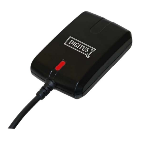
- Page 1 USB MOUSE GPS RECEIVER USER’S GUIDE...
-
Page 2: Table Of Contents
Contents 1. Introduction ……………………………………………………..…………. 2 1.1 Overview ………………………………………………………………………2 1.2 Features ………………………………………………………………..………2 1.3 Electrical Characteristics …………………………………………………… 2 2. Hardware Interface …………………………………………………………. 4 2.1 Dimension …………………………………………………………………… 4 2.2 Interface ………………………………………………………..…………….. 4 2.3 Connector …………………………………………………………...…..……. 5 3. Operation ……………………………………………………………………. 6 3.1 USB Driver Installation and Com Port Searching ………………………….. 6 3.2 Getting Start …………………………………………………………………10 3.3 Viewer for Testing ………..…………………………………………………... -
Page 3: Introduction
1 second (average) and updates position data every second. 1.2 Features The DA-80101 series provides a host of features that make it easy for integration and use. With SiRF StarⅢ high sensitivity chipset. High performance receiver tracks up to 20 satellites. - Page 4 Sensitivity Tracking -159 dBm typical Accuracy Position < 10 meters, 2D RMS < 7 meters 2D RMS, WAAS corrected 1-5 meters, DGPS corrected Time 1 m icrosecond sync hronized to GPS time Datum Default WGS-84 Acquisition Rate (Open Sky) Hot start 1 sec, average Warm start 38 sec, average...
-
Page 5: Hardware Interface
The receiver enclosure is with the dimension: 59.7 mm (L) x 39 mm (W) x 16.4 mm (H) 2.2 Interface The DA-80101 series GPS receiver includes a variety of models. The main difference is the output connector. These interface options are described in the following. DA-80101 DA-80101 is with a PS2 DIN jack output connector. -
Page 6: Connector
The Y cable is with one branch of PS2 Plug to connect to the PS2 Jack of DA-80101, while the other branch to connect to a PDA. However, due to the many variety of PDAs, an appropriate adaptor type must be specified. -
Page 7: Operation
3.1 USB Driver Installation and Com Port Searching For DA-80101 series GPS receiver using the USB type terminal, you have to install the driver first. Here we use WinXP OS as an example. Please insert the installation CD into CD-ROM drive. You... - Page 8 Please open the folder and double click the PL-2303 driver icon. The installation will start. Please click the “Next” button on the InstallShield Wizard’s “Welcome” window. Once the InstallShield Wizard completes the installation of the driver to your system, please click “Finish”...
- Page 9 You can plug the receiver’s USB terminal into USB port on your PC or NB now. However, for receiving the GPS data stream properly, you have to set the correct Com port and Baud rate in the utility software. Here is an easy approach for finding which Com port the mouse is connecting to. Please click Start →...
- Page 10 Click the “Hardware” tab and find the “Device Manager” button on the page. Click the button and the window will show the hardware status. Please find the “Ports (Com & LPT)” category and look for the Com port shown “Prolific USB-to-Serial Com Port (COMxx)”, the is the Com port number you are connecting to.
-
Page 11: Getting Start
Windows operating systems. 3.2 Getting Start Connect the DA-80101 GPS receiver with an appropriate adaptor assembly. It depends on the type of power source and host device. Install USB driver first when you connect to a host device with a USB adaptor cable. -
Page 12: Viewer For Testing
3.3 Viewer for Testing Install appropriate viewer program to host device. You may check the status of the GPS receiver whenever you like to. Following are standard buttons and operation steps. (a) Execute the Viewer program. Press the “COM” button to set “Com Port” for this data link and “Baud Rate”... -
Page 13: Function
3.4 Function As soon as the power on, the DA-80101 series GPS receiver begins the process of satellite acquisition, and tracking. Under normal circumstances, it takes around 42 seconds (average) to achieve a position fix at the first time. After a position fix has been calculated, information about valid position, velocity, and time is transmitted over the output channel. -
Page 14: Appendix: Software Specifications
Appendix: Software Specifications NMEA Protocol The DA-80101 interface protocol is based on the National Marine Electronics Association (NMEA) interface specification, namely, the NMEA 0183 standard. The DA-80101 is capable of supporting following NMEA message formats specifically developed and defined by SiRF. - Page 15 $GPGGA This message transfers global positioning system fix data. Following is an example. $GPGGA,161229.487,3723.2475,N,12158.3416,W,1,07,1.0,9.0,M, , , ,0000*18 The $GPGGA message structure is shown below: Field Example Unit Notes Message ID $GPGGA GGA protocol header. UTC Time 161229.487 hhmmss.sss Latitude 3723.2475 ddmm.mmmm N/S Indicator N=north or S=south.
- Page 16 $GPGLL This message transfers geographic position, latitude, longitude, and time. Following is an example. $GPGLL,3723.2475,N,12158.3416,W,161229.487,A,A*41 The $GPGLL message structure is shown below: Field Example Unit Notes Message ID $GPGLL GLL protocol header. Latitude 3723.2475 ddmm.mmmm N/S Indicator N=north or S=south. Longitude 12158.3416 dddmm.mmmm...
- Page 17 $GPGSA This message transfers DOP and active satellites information. Following is an example. $GPGSA,A,3,07,02,26,27,09,04,15, , , , , ,1.8,1.0,1.5*33 The $GPGSA message structure is shown below: Field Example Unit Notes Message ID $GPGSA GSA protocol header. M: Manual, forced to operate in selected 2D Mode or 3D mode.
- Page 18 $GPGSV This message transfers information about satellites in view. The $GPGSV message structure is shown below. Each record contains the information for up to 4 channels, allowing up to 12 satellites in view. In the final record of the sequence the unused channel fields are left blank with commas to indicate that a field has been omitted.
- Page 19 $GPMSS This message transfers information about radio beacon signal-to-noise ratio, signal strength, frequency, etc. Following is an example. $GPMSS,55,27,318.0,100,1,*57 The $GPMSS message format is shown below. Field Example Unit Notes Message ID $GPMSS MSS protocol header. Signal Strength SS of tracked frequency. Signal-to-Noise Ratio SNR of tracked frequency.
- Page 20 $GPRMC This message transfers recommended minimum specific GNSS data. Following is an example. $GPRMC,161229.487,A,3723.2475,N,12158.3416,W,0.13,309.62,120598, ,*10 The $GPRMC message format is shown below. Field Example Unit Notes Message ID $GPRMC RMC protocol header. UTC Time 161229.487 hhmmss.sss Status A: Data valid or V: Data invalid. Latitude 3723.2475 ddmm.mmmm...
- Page 21 $GPVTG This message transfers velocity, course over ground, and ground speed. Following is an example. $GPVTG,309.62,T, ,M,0.13,N,0.2,K,A*23 The $GPVTG message format is shown below. Field Example Unit Notes Message ID $GPVTG VTG protocol header. Course (true) 309.62 degree Measured heading Reference T = true heading Course (magnetic)
- Page 22 $GPZDA This message transfers UTC Time and Date. Following is an example. $GPZDA,181813,14,10,2003,00,00*4F The $GPZDA message format is shown below. Field Example Unit Notes Message ID $GPZDA ZDA protocol header. Either using valid IONO/UTC or estimated UTC Time 181813 from default leap seconds. UTC Day 01 to 31, day of month.
Need help?
Do you have a question about the DA-80101 and is the answer not in the manual?
Questions and answers