LM Technologies LM048 Manual
Bluetooth rs232 serial adapter
Hide thumbs
Also See for LM048:
- Manual (26 pages) ,
- At command manual (16 pages) ,
- Quick start manual (9 pages)

Related Manuals for LM Technologies LM048


Summary of Contents for LM Technologies LM048
- Page 1 Bluetooth RS232 Serial Adapter Manual Document Version: 1.3 Firmware Version: 6.5x LM048 LM058...
- Page 2 Document History Revision Date Name Description 25-03- Initial version 2011 16-05- Add CE Certificates 2011 15-02- 1. Add LM058 Hardware 2012 Structure 2. Update LM149 Configuration Software screenshot 14-05- Added FCC Regulation 2013 Statement...
-
Page 3: Table Of Contents
RS232 Interface Page 3 Pin-out Page 3 Signals Page 3 Factory Settings Page 3 Installation Page 4 LM048 Hardware Structure Page 4 LM058 Hardware Structure Page 4 Reset Button Page 5 Slide Switch Page 5 Power Supply Page 5 Antenna Connector (LM058 only) -
Page 4: Introduction
Introduction Welcome to the LM Technologies Bluetooth RS232 Serial adapter. The LM048/LM058 adapter eliminates your conventional RS232 serial cables, providing an easy-to-use, invisible connection with superior freedom of movement. This adapter allows any device with a standard 9-pin serial port to communicate wirelessly. -
Page 5: Package
Package Bluetooth serial adapter DB9 male to female converter USB cable for power supply User manual Warranty Card 2Dbi Antenna (LM058 only) Optional: 9 pin to 25 pin converter All in one power supply (UK, EU and US Plug) General Specification Specification Description Baud Rate... -
Page 6: Rs232 Interface
Dimensions LM048: 46.3 mm (W) x 34 mm (D) x 16 mm (H) LM058: 35 mm (W) x 65 mm (D) x 16 mm (H) RS232 Interface Pin-out Signals DTE to DCE DCE to DTE Description Signal Direction Direction Input... -
Page 7: Installation
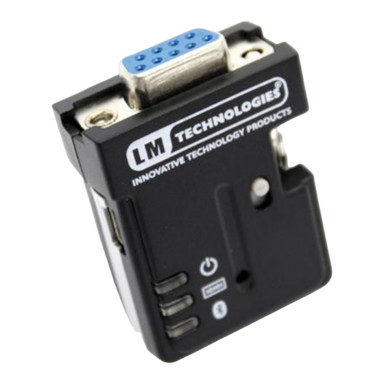
Installation LM048 Hardware Structure The figure below is an outline of the adapter. 1. Link LED 2. Data LED 3. Power LED 4. Mini USB connector 5. RS232 6. Slide Switch 7. Reset Button connector LM058 Hardware Structure 1. Power LED 2. -
Page 8: Reset Button
Reset Button By pressing the Reset button, you can: Disconnect and reconnect a wireless connection (after a short press). Restore the factory settings (after over three seconds’ press). Slide Switch The slide switch can swap TXD/RXD, RTS/CTS and DTR/DSR signals. Using this switch, you can set the adapter either as a DTE (towards antenna connector) or a DCE (towards RS232 connector). -
Page 9: Installation Procedure
Installation Procedure Step 1: Plug the adapter into the COM port of device. Step 2: Adjust the slide switch, depending on whether the device is a DCE or DTE. Step 3: Power the adapter on. Step 4: Configure the adapter using LM149 Software if necessary. Note: The UART settings on adapter should match the COM Port settings on the device. -
Page 10: Master Role Configuration
Master Role Configuration You can use “AT+ROLEM” to change the adapter to the master role. When the adapter is in the master role, you can use “AT+ACON-” to manually set up a connection and “AT+FIND?” to find the device you want to connect. - Page 11 Command Description Switch the device from online Data mode to online command mode while maintaining the connection to the remote device. The characters should be send with 1000 ms guard time.. Check the serial port communication with the adapter Inquire the current firmware version AT+VER Lists all the settings along with their brief description.
- Page 12 For security purpose, this command is used to specify a unique remote Bluetooth serial adapter to be connected. In the master role, the adapter pairs and connects with AT+BOND the designated remote slave address. In the slave mode, this command is a filter condition to accept the inquiry of the master device.
- Page 13 Specify whether the adapter can be discovered by remote AT+DCOV device. Changing this value causes a reboot. AT+DCOV+ (default) Device is in discoverable state. AT+DCOV- Device is non discoverable. AT+DCOV? Inquire the current discoverability status. Specify whether result messages are prompted when AT commands are executed.
- Page 14 Enable/disable auto-power saving feature of adapter AT+SLEEP AT+SLEEP- (default) Disable auto power saving AT+SLEEP+ Enable auto power saving AT+SLEEP? Inquire the current setting. Specify one or two stop bits of COM port. AT+STOP AT+STOP1(default) One stop bit. AT+STOP2 Two stop bits. AT+STOP? Inquire the current setting.
-
Page 15: Modem Signal Settings
DTR<->DSR between host and adapter, and NOT transferred to remote side wirelessly. DTR looped back to DSR. This configuration is equivalent to LM048 adapter running v4.5x firmware. FLOW- MODEMR Tx, Rx, GND, All 7 signals used. All RTS(R), CTS(R),... -
Page 16: Windows Configuration Software
LM048/LM058 RS232 Bluetooth serial adapters. To start the configuration software click “Read Settings” or “Get Device Info” in order to view current settings of LM048/LM058 adapter. Once you have setup the configuration that you require you will then need to click “Save Settings” or “Program Device”. - Page 17 The LM048/LM058 can also be paired via the configuration program using the “Pairing” button. It takes you to the page which provides option for Pairing/Unpairing adapters. If you want to set the adapter back to the factory default settings please click the “Restore Factory Settings” button.
-
Page 18: Warranty And Disposal Notice
Warranty and Disposal Notice One (1) Year International warranty Your LM Technologies LM048/LM058 is warranted by your supplier for a period of one (1) year from the original data of purchase under the terms and conditions of this warranty. This warranty covers materials and manufacturing defects. -
Page 19: 10. Fcc Regulation Statement
10. FCC Regulation Statement This device complies with Part 15 of the FCC Rules. Operation is subject to the following two conditions: 1) This device may not cause harmful interference, and 2) This device must accept any interference received, including interference that may cause undesired operation This equipment has been tested and found to comply with the limits for a class B digital device, pursuant to part 15 of the FCC... - Page 20 Manufacturer and its authorized resellers or distributors will assume no liability for any damage or violation of government regulations arising from failing to comply with these guidelines. This equipment complies with FCC radiation exposure limits set forth for an uncontrolled environment. This transmitter must not be co-located or operating in conjunction with any other antenna or transmitter.
-
Page 21: Lm048 Ce Certificate
Page 18... -
Page 22: Lm058 Ce Certificate
Page 19... - Page 23 Copyright © LM Technologies Ltd - 2013...
- Page 24 Interface Development Tools Click to view products by manufacturer: LM Technologies Other Similar products are found below : CY4607M PEX 8748-CA RDK DP130SSEVM ISO3086TEVM-436 SP338EER1-0A-EB ADM00276 ADP5585CP-EVALZ PEX8724-CA RDK PEX 8732-CA RDK PEX8747-CA RDK AS8650-DB MLX80104 TESTINTERFACE I2C-CPEV/NOPB ISO35TEVM-434 KIT33978EKEVB 416100120-3 XR17D158CV-0A-EVB XR17V358/SP339-E4-EB XR17V358/SP339-E8-EB XR18910ILEVB XR22804IL56-0A-EB ZSC31050KIT V3.1 ZSC31150KIT V1.2 SCRUBBER-EVM SI838XISO-KIT 73931-3022 XIO2200AEVM XIB-E...
Need help?
Do you have a question about the LM048 and is the answer not in the manual?
Questions and answers