Table of Contents
Advertisement
Quick Links
General
Installation/Wiring
DIGITAL CONVERSION MODULE
Changeover of mode
CSD-892-73
Instruction Manual
Calibration
Setting of Function
Setting of Comparator
Check mode
CC-Link interface
USB (RS-232C) interface
Trouble shooting
Specifications & others
Minebea Co., Ltd.
Measuring Components Business Unit
EN294-1540
Advertisement
Chapters
Table of Contents

Related Manuals for Minebea CC-Link CSD-892-73


Summary of Contents for Minebea CC-Link CSD-892-73
- Page 1 General Installation/Wiring DIGITAL CONVERSION MODULE Changeover of mode CSD-892-73 Instruction Manual Calibration Setting of Function Setting of Comparator Check mode CC-Link interface USB (RS-232C) interface Trouble shooting Specifications & others Minebea Co., Ltd. Measuring Components Business Unit EN294-1540...
-
Page 2: Foreward
FOREWARD Thank you very much for your purchasing Minebea's Digital Conversion module, model CSD- 892-73. This manual for CSD-892-73 explains the procedures and checkpoints in operation. We would like you to read through this instruction manual with much care for the best use of our product to avoid malfunctions. -
Page 3: For Safe Operation
For safe operation Be sure to read this manual before use. 1. Location of installation Caution • Use the Instrument under the following conditions. Environmental temperature:-10 ℃ ~ 50 ℃(Preservation:-20 ℃ ~ 60 ℃) ● Environmental humidity:85 %RH or less. (Non-condensing) ●... -
Page 4: Installing The Instrument
2. Installing the instrument When you set up two or more devices, you can install on the same panel with no clearance in between. Caution • Please secure and set up the space between this instrument and the device ■ Outline dimensions Front Side 67.4... -
Page 5: Power Supply
ON, operator may have an electric shock or the instrument may be destroyed. • Before supplying power, check the indication of power voltage/specifications to be identical with supplied power. If they are not identical, contact with Minebea. Without checking the above, operation may cause damage to the instrument or electric shock. - Page 6 • At the time of shipment from the factory, the instrument has been plated with a clear sheet on the panel sheet for protective purpose. In case of application, use the instrument after removing the clear sheet first. • Do not push the panel sheet on the instrument with the excessive strong force nor push it with sharp edge object such as a driver.
-
Page 7: Revision History
Revision history Date Instruction No. Reason of revised (Contents) 2012/08 DRW. NO. EN294-1540 First version... -
Page 8: Table Of Contents
CONTENTS FOREWARD ..................I Marks and references described in this manual........ I For safe operation ................II Location of installation ..................II Installing the instrument ..................III Power supply ....................... IV Instruction for usage .................... IV Conformity standard ....................V Revision history ................VI 1. - Page 9 5. C function mode ................35 5-1. Setting method of C function mode ..............35 5-2. Details of C function data ..................36 6. Various operations by C function data .......... 38 6-1. Decimal point display position ................38 6-2. A/D sampling ......................38 6-3.
- Page 10 10. Various operations by S function data ........58 10-1. Measurement mode ..................... 58 10-2. Control mode ....................... 58 10-3. Operation of comparative signal ................58 10-4. Comparative operation at NEAR ZERO (ZERO BAND) ........10-5. Comparative operation of FULL ................58 10-6.
- Page 11 16-2. Operation mode ....................111 16-3. Command data format ..................113 16-4. Data format for stream mode ................125 16-5. Data format of calibration by transmission ............127 17. Trouble shooting ............... 136 17-1. Basic chapter ...................... 136 17-2. External control I/O chapter ................137 17-3.
-
Page 12: Each Name And Function
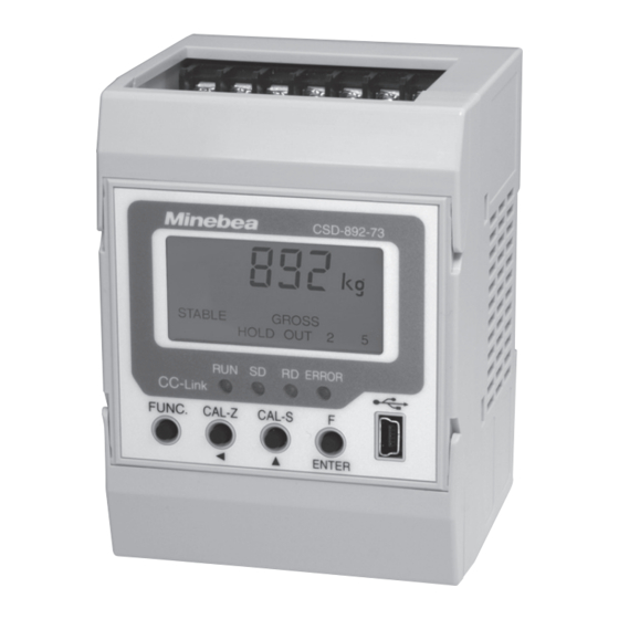
1. Each Name and Function 1-1. Front panel ① Unit display ② Load display ③ Condition display ④ Status LED ⑨ USB interface connector ⑤ FUNC. key ⑧ F/ENTER key ⑥ CAL-Z/ ⑦ CAL-S/ ▲ key ① Unit display section Display the setting unit of weighing. - Page 13 The subject driver installation is needed. Please download from Minebea's homepage, and install it to the PC. Additionally, EzCTS_USB1 (Optional software for PC) is convenient for reading, writing, saving and printing the setting data by connecting with PC.
-
Page 14: Upper And Lower Part Of Front Panel
1-2. Upper and lower part of front panel CC-Link interface connector Terminals for load cell Terminals for power supply and (Upper part terminals) external control I/O (Lower part terminals) Cover-1 and -2 of terminal block ① Cover-1 and -2 of terminal block This is the protection cover of upper / lower terminal blocks. -
Page 15: Installation And Wiring
2. Installation and Wiring 2-1. Attaching to and Removing from a DIN rail This instrument adopts the rail mounting type with 35 mm width of DIN standard. The procedures of attaching and removing are as follows: Attaching method to a DIN rail ①... -
Page 16: Connection With Strain Gage Based Transducer
Load cell input - (Blue) Shield (Yellow) • When the length of CAB-501 (Minebea's standard cable) is more than 100 m totally, the accuracy may be out of warranty as the remote sensing function of the instrument does not work enough due to the resistance of the cable. - Page 17 F and G is in the open status. • When the length of CAB-502 (Minebea's standard cable) is more than 30 m totally, there may have the case that the accuracy is out of warranty due to the resistance of cable, the input voltage of the instrument will be decreased.
- Page 18 ③ Case connection of the load cells in parallel The hopper scale, the track scale, etc, have the case to connect with several pieces of the load cells in parallel. The parallel connections can be easily executed by using optional SB-310 and SB-320 (Summing type junction box).
- Page 19 • The remote sensing function of the instrument does not function enough due to the resistance of the cable at the time of total 100 m or more in length of CAB- 501 (Minebea's standard cable), and there may have the possibility of outside the accuracy guarantee.
- Page 20 C-G of the load cell terminal board. When terminal F and terminal G are used with opening status, CSD-892-73 cannot make normal operation. • When the length of CAB-502 (Minebea's standard cable) is more than 30 m totally, the accuracy may be out of warranty due to the resistance of cable, the input voltage of the instrument will be decreased.
-
Page 21: Connecting Of Power Supply And Ground
2-4. Connecting of power supply and ground Please connect the power supply and ground to the lower terminal block as shown in the following figure. Frame ground F.G. +24 V Power supply DC24V Power supply DC V D-class with DC24V single earth (Permissible variable range : DC20.4 V ~ DC27.6 V) CAUTION... -
Page 22: Connection With External Control I/O
2-5. Connection with external control I/O You can control the function from the external control I/O terminals (Lower terminal block). The external control input is executed by shortening each input and COM1 with a contact point or open collector after wiring the connector. The external control output is an open electron collector output.(Open collector ratings V = DC35 V, I = DC50 mA MAX)... -
Page 23: Connection Of Cc-Link Interface
2-6. Connection of CC-Link interface The cable only for CC-Link is wired to the attached connector for CC-Link, and connected as shown in the figure below. For connection of CC-Link cable, use a twisted pair cable line with shield (Cable only for ●... -
Page 24: Operation
3. Operation 3-1. Changeover of mode CSD-892-73 has various modes according to the operating situation. Please push the [F/ENTER] key when you display the mode that shifts with the [CAL-Z/ ] key and the [CAL-S/ ▲ ] key after pushing the [FUNC] key. Please refer to [3-2. - Page 25 ① Function mode The setting concerning the following functions and (FUNC) effective/invalid are changed. • Various filter • Key lock • Detection of stability • Hold • Set of action for five steps comparator • Allocation of function to [F/ENTER] key. •...
-
Page 26: Display Transition Diagram
3-2. Display transition diagram Measurement mode key pushing movement ▶ ENTER ENTER ▶ CAL-Z CAL-Z key pushing movement FUNC. FUNC. key pushing movement ▶ * * ▶ Function mode (F -**) (FUNC) * * ▶ C-function mode (CF-**) (CFUNC) * * ▶... -
Page 27: Calibration Mode
4. Calibration mode 4-1. What is calibration? The calibration is an operation that matches the load of the sensor to the display of this instrument to display the electrical signal from the sensor (load cell) as an accurate load. If the calibration is not proceeded, a correct display and an output cannot be taken. The example when the load cell is used is shown as follows. -
Page 28: Procedure Of Calibration
4-2. Procedure of calibration Please refer to [4-6. Details of calibration procedure] for the actual steps. After turning on DC24V, CSD-892-73 is Advance preparation energized for about 10 minutes to stabilize Turn on power supply CSD-892-73 and weighing section (load cell). Step Switch from measuring mode to the calibration mode. - Page 29 • The environment used must execute the calibration again if necessary in altered case. • When Minebea has executed the calibration in the combination with load cell, you don't need to execute the calibration again. • Execute the calibration with actual load when you can prepare the weight of 2/3 or more of weighing capacity.
-
Page 30: Selection Of Calibration Method
4-3. Selection of calibration method The procedure is different according to the using condition and presence of weight as for [Step 7 ZERO calibration] and [Step 8 SPAN calibration]. Calibration of ZERO ● In the normal using condition, ZERO calibration by measuring value (Actual load calibration) is executed. -
Page 31: Details Of Calibration Procedure
4-6. Details of calibration procedure We explain the calibration procedures from a condition of factory shipment. For example, we explain by the case that the maximum display value is 6.000 t, and the scale interval is 0.002 t. Step Switch to the calibration mode Measurement mode 1... - Page 32 Step Set of decimal point display position 1 When key is pushed at ENTER is displayed. * The position of decimal point memorized now is displayed. The position memorized Select the position of decimal point. CAL-Z CAL-Z CAL-S CAL-S Select the position by key.
- Page 33 Step Set the weighing capacity When key is pushed at display, ENTER is displayed. * The weighing capacity memorized now is displayed. The weighing capacity memorized now. Set the weighing capacity. CAL-Z CAL-Z Select the changed digit. Set-up weighing capacity CAL-S CAL-S Increment the value of selected digit.
- Page 34 ZERO is registered by reading the load cell output value in the Step (Actual weight calibration) condition that nothing is put on the measuring part (Initial condi- ZERO Calibration by measurement value tion including tare). Please select the method of ZERO calibration referring to [4-3. Selection of Calibration Method] 1...
- Page 35 Step (Actual weight calibration) SPAN is registered by reading the output value in the condition to SPAN calibration by the weight put the weight set according to step 6. Please select the method of SPAN calibration referring to [4-3. Selection of Calibration Method] 1...
- Page 36 Step End of calibration 1 displays after the span calibration is finished. Push key to complete the calibration mode. ENTER The display becomes , and the set data is memorized internally. FUNC. FUNC. Measurement mode By pushing key twice, return to the measurement mode. •...
-
Page 37: Fine Adjustment Of Zero And Span
4-7. Fine adjustment of ZERO and SPAN This function fine-adjusts ZERO and SPAN when there is any difference margin in an actual weighing capacity and the mass of weight. You can register only of either the ZERO or SPAN. We explain the procedures for fine adjustment of SPAN after the fine adjustment of ZERO as follows. - Page 38 Step to fine adjustment of SPAN 1 By pushing key from ENTER ENTER blinks. * The present measurement value is displayed. Please put the weight that can be put on the measuring part below weighing capacity, and adjust the display to become the value equal to mass of weight.
-
Page 39: Digital Linearization
4-8. Digital linearization After the calibration, the measurement error of some scale interval levels might be caused between ZERO and SPAN (maximum capacity) by the influence of the measuring section etc.The digital linearization function executes the compensation of three points or less except ZERO and SPAN, and to reduce the measurement error. - Page 40 Step Setting of digital linearization 1 By pushing key twice from display, ENTER ENTER → Display changes in order of → As the display becomes by pushing → CAL-S CAL-S key from display, please select the numbers of points which wants to compensate linearization, and press key.
-
Page 41: Calibration Only Of Zero
4-9. Calibration only of ZERO This function is for calibrating again only of the ZERO when the amount of the tare other than the maximum capacity of the measuring part are changed. Step Change to calibration mode only for ZERO Measurement mode 1... -
Page 42: Simple Calibration
4-10. Simple calibration Each item can be immediately shifted to a set screen and the calibration screen by pushing CAL-S CAL-S FUNC. FUNC. CAL-Z CAL-Z key for about 2 second or more. • Please use the simple calibration function after releasing the lock referring to [4- 10-1. - Page 43 4-10-2. Setting mode By pushing key for 2 seconds or more, you can set the unit, decimal point display position, scale interval, weighing capacity, ZERO calibration, SPAN calibration (both are calibration by numeric input). When the display blinks while setting the item and the item is fixed with the [F/ENTER] key, the display becomes a lighting display.
- Page 44 4-10-3. ZERO mode ZERO calibration is executed by reading the load cell output value at ZERO by pushing CAL-Z CAL-Z key for 2 seconds or more. Measurement mode CAL-Z CAL-Z CAL-Z CAL-Z Push for 2 By pushing key for 2 seconds or more from the normal seconds or more measurement mode, blinks.
- Page 45 4-10-4. SPAN mode The setting of weighing capacity and mass of weight, and span calibration by reading the CAL-Z CAL-Z load cell output value is executed by pushing key for 2 seconds or more. Measurement mode CAL-S CAL-S CAL-S CAL-S Push for 2 By pushing key from the normal measurement mode,...
-
Page 46: C Function Mode
5. C function mode By setting of C function, the setting of the function related to the calibration, and changeover of valid / invalid is executed. 5-1. Setting method of C function mode Measurement mode 1 FUNC. FUNC. By pushing key from the normal measurement mode, displays. -
Page 47: Details Of C Function Data
5-2. Details of C function data Reference No. Item Function No. Set value Contents ● 0 No decimal point 1234.5 Display position of CF-01 123.45 decimal point 12.345 1.2345 50 times/s 100 times/s A/D sampling rate CF-02 250 times/s ● 3 500 times/s At exceeding | Weighing capacity + 9D | Condition of overload... - Page 48 Reference No. Item Function No. Set value Contents ● 0 Invalid Stability detection in the 6-11 CF-20 setting. Valid ● 0 Set the district number Method of setting 6-12-1 gravity acceleration CF-25 Set the numerical value of gravity acceleration compensation CF-26 01~16 Unit : District...
-
Page 49: Various Operations By C Function Data
6. Various operations by C function data 6-1.Decimal point display position The decimal point display position is selected by C function CF-01. Setting range : 0 ~ 4 0:Nothing 1:1234.5 2:123.45 3:12.345 4:1.2345 6-2.A/D sampling The A/D sampling rate is selected by C function CF-02 Setting range:0 ~... -
Page 50: Zero Set
6-6.ZERO set ZERO set function memorizes a present measuring value as ZERO when the indicated value of the load display section is the gross display and within the effective range of ZERO set, and adjust the display to zero. This function is used by pushing [F/ENTER] key allocated (Refer to function F-55), or used as the external control after allocating to the external control input (Refer to function F-60 ~ F-62). - Page 51 6-7-3. Time width of ZERO tracking The time width of ZERO tracking is set by C function CF-14. Setting range : 00 ~ 99 :00 Unit : 0.1 s OFF:00 Ex. The data width to which the ZERO tracking is executed by C function CF-13 is set. The data width of ZERO tracking for each set value [n] is obtained in the display conversion by the following formula [Data width of ZERO tracking] = [Set value(n) of CF-13] x 0.1 x [Scale interval]...
-
Page 52: Power On Zero
6-8.Power on ZERO The power on ZERO function makes the display to a zero if the changes of display is within ± 10 % of the maximum capacity when the power is turn on, or in the stable condition in the operation of display turning on. -
Page 53: Change Of Data Stored Place
6-10. Change of data stored place The data stored place of [Internal RAM] or [EEPROM] is selected by C function CF-17. Setting range:000 ~ 111 :100 0:Internal RAM 1:EEPROM * Each digit of the set value corresponds to the following items, and selects stored place of each digit. - Page 54 6-12-2. Setting of district number of the using place (CF-25:0) The district number of the using place is set by C function CF-26. Please refer to the below list. Setting range:01 ~ 16 :No.10 district 6-12-3. Setting of district number of calibration place (CF-25:0) The district number of calibration place is set by C function CF-27.
-
Page 55: Calibration Data (For Reference)
6-13. Calibration data (For reference) Scale interval, Weighing capacity, Mass of weight, ZERO mV/V value and SPAN mV/V value set at present is referred by C function CF-90 ~ CF94. 6-14. Stability detection time width in calibration Stability detection time width in calibration is set by C-function CF-97 Setting range : 00 ~... -
Page 56: Function Mode
7. Function mode Various functions become effective by setting the function data. 7-1. Setting method of function mode Measurement mode 1 FUNC. FUNC. By pushing key from normal measurement mode, the display becomes and you can enter into the function mode. By pushing key, displays. -
Page 57: Details Of Function Data
7-2. Details of function data Reference No. Item Function No. Set value Contents 001 ~ 512 Digital filter F-01 Unit : Moving average time 1 time ● 016 2 Hz ● 1 4 Hz Analog filter F-02 6 Hz 8 Hz 10 Hz 001~512 8-3-1... - Page 58 Reference No. Item Function No. Set value Contents ● 0 Command mode Operation mode of USB 16-2-1 F-40 (RS-232C) Stream mode Synchronizing with display ● 0 (HOLD at HOLD signal ON) F-41 Output target in stream Gross value 16-2-2 (effective at mode of USB (RS-232C) F-40=1) Net value...
- Page 59 Reference No. Item Function No. Set value Contents ● 00 STABLE DURING TARE WEIGHT CANCELLATION DISPLAY GROSS VALUE DISPLAY NET VALUE CENTER ZERO DURING HOLD ERROR Operation of external CAPACITY EXCEED ERROR 8-8-2 control output F-70 NEAR ZERO (OUTPUT1) OK (S0) FULL FLOW (S1) MIDIUM FLOW (S2) DRIBBLE FLOW (S3)
-
Page 60: Various Operations By Function Data
Various operations by function data 8-1. Digital filter The function of digital filter is a steady of A/D converted data by the running average processing. The running average frequency is selected by the setting of function F-01. Setting range:001 ~ 512 :016 Unit:1 times The tendency to the characteristic by running average is shown in the table below. - Page 61 Ex. The data width to which the stabilization filter is executed is selected by function F-06. The data width of stabilization filter for set value [n] is obtained in the display conversion by the following formula. [Data width of stabilization filter]=[Set value(n) of F-06]x[Scale interval] When the setting of function F-06 is [0010] (1D) and the scale interval is [D=05], this will be as follows: [Data width of stabilization filter] = 1 x 5 = 5D...
-
Page 62: Key Lock Function
8-4. Key lock function This function limits the operation to prevent the operational error of various keys at a front panel. Condition indicator lights on when each key lock function becomes effective. 8-4-1. Individual key lock [VALID] or [INVALID] of the operation for [FUNC.] key, [CAL-Z/ ] key, [CAL-S/ ] key and [F/ENTER] key is set by function F-08. -
Page 63: Hold
8-6.Hold This function retains the measurement value and comparison result during the operation. The HOLD signal can be input by the method of allocating the HOLD function to [F/ENTER] key, and otherwise, by using the external control input. The condition display lights on while holding. -
Page 64: External Control I/O
8-8.External control I/O The external control I/O is set. 8-8-1. Setting of external control input The operation of external control input is selected by the setting of function F-60 ~ F62. Setting range:00 ~ 10 :00 00:OFF No setting 01:ZERO set Execute the operation of ZERO set 02:ZERO clear When ZERO set and ZERO tracking is executed,... - Page 65 8-8-2.Setting of external control output The operation of external control output is selected by the setting of function F-70 ~ F-74 Setting range:00 ~ 17 :00 00:OFF No setting 01:STABLE Output during stable 02:DURING TARE Output when tare weight cancellation is executed. 03:GROSS DISPLAY Output when display is the gross value.
-
Page 66: Maintenance Date, Maintenance Number
8-9. Maintenance date, Maintenance number Please do not use because F-90 and F-91 are functions for our maintenance. 8-10. Lighting time of liquid crystal back light Lighting time of liquid crystal back light is set by function F-95. When the set time has passed since the key was operated at the end, back light of liquid crystal is turned off. -
Page 67: S Function Mode
9. S function mode The changeover of measurement mode, the changeover of control mode, the operation of comparison signal, the comparison operation of near zero, the comparison operation of full are set in S function mode. Please refer [11. Measurement mode] for the details of measurement mode and control mode. -
Page 68: Details Of S Function Data
9-2. Details of S function data Referenced Function Item No. Setting value Contents Simple comparison mode 10-1 Measurement mode SF-01 ● 1 5 steps comparator mode ● 0 Batch mode 10-2 Control mode SF-02 Discharge mode Any time Operation of comparative 10-3 SF-05 signal... -
Page 69: Various Operations By S Function Data
10. Various operations by S function data 10-1. Measurement mode The measuring mode is selected by the setting of S function SF-01. Setting range:0,1 0:Simple comparison mode (Batch/Discharge mode) 1:5 steps comparator mode 10-2. Control mode The Control mode (Batch/Discharge mode) is selected by the setting of S function SF-02. Selecting range:0,1 0:Batch mode 1:Discharge mode... -
Page 70: Measurement Mode
11. Measurement mode CSD-892-73 consists of two(2) measurement mode as [Simple comparison mode] and [5 steps comparator mode], and furthermore, [Simple comparison mode] includes [Batch mode] and [Discharge mode]. The comparison result of the set value and the measuring value can be output by selecting either of mode, and also setting the necessary parameter. -
Page 71: Selection Method Of Measurement Mode
11-1. Selection method of Measurement mode Either the simple comparison mode or the 5-steps comparator mode is selected. Measurement mode 1 FUNC. FUNC. By pushing key from the normal measurement mode, displays. CAL-Z CAL-Z Push key twice. The display changes in order of → → ... -
Page 72: Simple Comparison Mode
11-2. Simple comparison mode The simple comparison mode includes [Simple comparison batch mode] and [Simple comparison discharge mode]. Please select the set value [0] in the setting of S function SF-01 to use the simple comparison mode. Also, please refer to [11-2. Simple comparison mode for the selection of [Batch mode] and [Discharge mode]. - Page 73 11-2-1. Setting of measuring value (COMP. setting mode) The setting of measuring value used in Single comparison mode is executed. • Please execute after selecting a set value : [0] (Simple comparison mode) in the setting of S function SF-01. Measurement mode 1...
- Page 74 11-2-2. Set items of single comparison mode Item Set data number Setting value Contents 00000 ~ 99999 FINAL SET1 Unit : 1D ● 00000 00000 ~ 99999 FREE FALL SET2 Unit : 1D ● 00000 00000 ~ 99999 PRELIMINARY 1 SET3 Unit : 1D ●...
- Page 75 UNDER The value of UNDER is set by set data number SET6. The output of UNDER is turned on when the measurement result is falling below [FINAL(SET1 - UNDER(SET6)] Setting range : 00000 ~ 99999 :00000 Unit : 1D NEAR ZERO (ZERO BAND) The output value of NEAR ZERO signal is set by set data number SET7.
- Page 76 11-2-3. Simple comparison batching mode The simple comparison batching mode is an output mode when the result of comparing the increasing amount of measurement value in batching the measuring material with the set value meets the judgement condition. The set value : [0] (Batching mode) is selected by the setting of S function SF-02. Judgement condition Condition display Judgement condition...
- Page 77 11-2-4. Simple comparison discharge mode Simple comparison discharge mode is a mode output when the judgement condition that compares a decreasing amount in discharging a measurement material and a value to execute the setting is satisfied. The set value : [1] (Discharge mode) is selected by the setting of S function SF-02. Judgement condition Condition display Judgement condition...
-
Page 78: Steps Comparator Mode
11-3. 5 steps comparator mode The result of comparing up to 5 points of setting value and the measurement value is output. 11-3-1. Setting of comparison value (COMP. setting mode) The comparison value used in 5 steps comparator mode is set. •... - Page 79 11-3-2. Setting items of 5-steps comparator mode Items Set data number Set value Contents -99999 ~ 99999 Unit : 1D ● 00000 -99999 ~ 99999 Unit : 1D ● 00000 -99999 ~ 99999 Unit : 1D ● 00000 -99999 ~ 99999 Unit : 1D ●...
- Page 80 11-3-3. Operating condition of comparator S0, S1, S2, S3 and S4. The comparator in this mode, S0, S1, S2, S3 and S4 individually can select the operation whichever [More than setting value] or [Less than setting value]. These can be selected by function F-22 [Operating condition of 5-steps comparator]. Please refer [7-2.
- Page 81 11-3-4. Operating target of comparator S0, S1, S2, S3 and S4 The comparator in this mode, S0, S1, S2, S3 and S4 individually can select the comparison target from [Display synchronization], [GROSS value] or [NET value]. These can be selected by function F-21 [Operating target of 5-steps comparator]. Please refer [7-2.
- Page 82 11-3-5. Hysteresis of comparator Hysteresis can be set because the comparator S0, S1, S2, S3 and S4 prevent the chattering of each output (phenomenon that ON/OFF is repeated in detail when the signal divides the change). Hysteresis combines and uses the setting of data width and time width.
- Page 83 (3) When the operation of [Less than set value] with S0 is selected, and an effective direction of hysteresis is set to [ON delay]. Hysteresis time width S0 set value Hysteresis data width Time S0 output ON S0 output OFF (4) When the operation of [Less than set value] with S0 is selected, and an effective direction of hysteresis is set to [OFF delay].
-
Page 84: Stored Data Of Setting Data
12. Stored data of setting data In CSD-892-73, each data is stored in internal RAM and EEPROM as follows. The data in EEPROM can be stored almost permanent due to nonvolatile. 12-1. Data stored in internal RAM • Tare weight cancellation (Saving to EEPROM is also possible.) •... -
Page 85: Check Mode
13. Check mode The followings are confirmed in check mode. Shift to EzCTS mode ● Confirmation of ROM version ● Confirmation of external control input operation ● Confirmation of external control output operation ● Confirmation of load cell output voltage ●... -
Page 86: Ezcts Mode
13-2. EzCTS mode EzCTS is an application for the personal computer (EzCTS_USB1 as an option), and reading out and reading in the CSD-892-73 function data can be facilitated. This software is useful for maintenance and data back-up. 1 By pushing key from the display of ENTER ENTER... -
Page 87: Confirmation Of External Control Input
13-4. Confirmation of external control input 1 By pushing key from the display of ENTER ENTER the display of becomes blinking. Confirmed by At this time, ON/OFF condition of external control input ON/OFF of can be confirmed in the condition display section. external output When each input terminal of external control input (at lower terminal block) is ON, each condition display [1 ~ 3] lights on. -
Page 88: Confirmation Of Load Cell Output Voltage (Monitor Mode)
B-C-D-G of the upper terminal block after the strain gage based transducer had been removed steady? → Yes… The influence from the noise source such as inverters is thought. Please contact Minebea when the condition doesn't change even if you reconfirm the wiring. → No… Please inform the details to Minebea. -
Page 89: Cc-Link Interface
14. CC-Link interface 14-1. General This is a remote device station of CC-Link Ver 1.10. This unit can be connected with the mastering station of CC-Link Ver 1.10 14-2. Features Main futures of CC-Link interface communication are as follows: • The program volume of PLC can be reduced because this unit can be controlled by using remote I/O and a remote register of PLC. - Page 90 14-3-2. Station number The station number for CC-Link communication is set by function F-85. Setting range : 01 ~ 64 :01 When 1 station is occupied : Select from station number 01 ~ 64 When 2 stations are occupied : Select from station number 01 ~ 63 When 4 stations are occupied : Select from station number 01 ~ 61 Numbers of occupied station of this unit is 1, 2 or 4 stations.
-
Page 91: Plc Memory Explanation
14-4. PLC memory explanation A remote I/O (RX/RY : Bit handling register) and a remote register (RWw/RWr : Word handling register) secures the zone in the master station depends on the occupied station number. As shown in the table below in case of this unit. Occupied station number Type Remarks... -
Page 92: Address Map
14-5. Address map 14-5-1. Data detail 1) Batch/Discharge mode Remote register 4 stations occupied (Master → CSD-892-73) Station Remote register Contents Remarks RWwn ① Final (24 bit) RWwn+1 RWwn+2 ① Preliminary 2 (32 bit) RWwn+3 RWwn+4 ① Preliminary 1 (16 bit) RWwn+5 ①... - Page 93 ① Special data area (4 stations, 2 stations) When the set value is registered by using the set value writing request (Request 1), the set value is set in each area. Details of each set value are shown as follows; Data type Setting range Final...
- Page 94 2) Remote register of 5 steps comparator mode 4 stations occupied (Master → CSD-892-73 Station Remote register Contents Remarks RWwn ① S1 (32 bit) RWwn+1 RWwn+2 ① S2 (32 bit) RWwn+3 RWwn+4 ① S3 (32 bit) RWwn+5 Special data area RWwn+6 ①...
- Page 95 ① Special data area (4 stations, 2 stations) When the set value is registered by using the setting value writing request (request 1), the set value is set in each area. Details of each set value are shown as follows; Data type Setting range 32 bit binary with sign...
- Page 96 3) Command list The command No. and the value which is set in General data area when the command order is executed by using the general command request (request 2) are shown in the next page. Writing set value and command order (Writing/Reading selection = Writing [OFF]) Command No.
-
Page 97: Setting Value Or Command Order
Reading set value (Writing/reading selection = Reading [OFF]) Command No. General data area Setting value or command order (RWwnE) (RWwnC ~ RWwnD) Undefined Undefined Undefined Undefined Undefined Final / S1 Free fall / S4 Preliminary 1 / S3 Preliminary 2 / S2 Over / S0 Under Near zero... -
Page 98: Undefined
4) Remote register 4 stations occupied (CSD-892-73 → Master) Station Remote register Contents Remarks RWwn ① Net value RWwn+1 RWwn+2 ② Gross value RWwn+3 RWwn+4 Undefined RWwn+5 RWwn+6 ③ Error code RWwn+7 ④ Error assistance code RWwn+8 RWwn+9 Undefined RWwn+A RWwn+B RWwn+C ⑤... - Page 99 ① Net value (4 stations) Area for displaying the net value. Data type : 32 bit binary with sign Setting range : -99999 ~ 99999 ② Gross value (4 stations) Area for displaying the gross value. Data type : 32 bit binary with sign Setting range : -99999 ~ 99999 ③...
- Page 100 ⑤ General data area (4 stations, 2 stations) When the set value reading out command is ordered by using the general command request (Request 2), This area represents the set value. Data type : 32 bit binary with sign. ⑥ Command No. (Response) (4 stations, 2 stations) When the set value reading out command is ordered by the general command request (Request 2), this area represents that command No.
- Page 101 14-5-2. Relay zone 1) Remote input 4 stations occupied (Master → CSD-892-73) Device No. Contents Classification RYn0 ① Setting value writing request (Request 1) RYn1 RYn2 ② General command request (Request 2) RYn3 ③ Selection of writing/Reading out. (R/W) Communication RYn4 ④...
- Page 102 2 stations occupied (Master → CSD-892-73) Device No. Contents Classification RYn0 ① Setting value writing request (Request 1) RYn1 RYn2 ② General command request (Request 2) RYn3 ③ Selection of writing/Reading out. (R/W) Communication RYn4 ④ Operation mode changeover request (Request 3) RYn5 RYn6 RYn7...
- Page 103 1 stations occupied (Master → CSD-892-73) Device No. Contents Classification RYn0 ⑤ ZERO RYn1 ⑥ ZERO Clear RYn2 ⑦ Tare weight cancellation RYn3 ⑧ Tare weight cancellation clear Control signal RYn4 ⑨ Hold RYn5 RYn6 RYn7 ⑮ Indicate value changeover flag (Net value/Gross value) RYn8 RYn9 RYnA...
- Page 104 ③ Selection of writing or reading out (R/W) Writing or reading out is selected by the command order. Writing the data set in General data area (RWwnC ~ RWwnD) is ordered for writing by command No. (RWwnE) Reading out the data set in General data area (RWwnC ~ RWrnD) is ordered for reading out by command No.
-
Page 105: Zero
⑩ Display of net value The display is set to net value. : In requesting the display of net value (Operated once by OFF → ON). : Normal ⑪ Display of gross value The display is set to gross value. : In requesting the display of gross value (Operated once by OFF →... - Page 106 2) Remote output 4 stations occupied (CSD-892-73 → Master) Device No. Contents Classification RYn0 ① Setting value writing request (Request 1) RYn1 RYn2 ② General command request (Request 2) RYn3 ③ Selection of writing/Reading out. (R/W) Communication RYn4 ④ Operation mode changeover request (Request 3) RYn5 RYn6 ⑤...
- Page 107 2 stations occupied (CSD-892-73 → Master) Device No. Contents Classification RYn0 ① Setting value writing request (Request 1) RYn1 RYn2 ② General command request (Request 2) RYn3 ③ Selection of writing/Reading out. (R/W) Communication RYn4 ④ Operation mode changeover request (Request 3) RYn5 RYn6 ⑤...
- Page 108 1 stations occupied (CSD-892-73 → Master) Device No. Contents Classification RYn0 ⑦ Near Zero RYn1 ⑦ Full flow/S1 RYn2 ⑦ Medium flow/S2 RYn3 ⑦ Dribble flow/S3 Control signal RYn4 ⑦ Over/S4 RYn5 ⑦ OK/S0 RYn6 ⑦ Under RYn7 ⑦ Stable RYn8 RYn9 ⑧...
- Page 109 ① Setting value writing response (Response 1) The finish of writing by the Setting value writing request (Request 1) is notified. :In completion or writing OFF :After confirming OFF of Setting value writing request (Request 1). ② General command response (Response 2) The finish of writing by the Setting value writing request (Request 2) is notified.
- Page 110 ⑦ Near ZERO, and the other condition The conditions of NEAR ZERO, FULL FLOW/S1, MEDIUM FLOW/S2, DRIBBLE FLOW/ S3, PROPER VALUE/S0, UNDER, STABLE and FULL are notified. ⑧ Weighing capacity over This signal is notified when the abnormal condition occurs in the load (OL, OVF, -OL or -OVF).
-
Page 111: Calibration By Cc-Link Interface
14-6. Calibration by CC-Link interface When 4(four) and 2(two) stations are occupied, the calibration by the CC-Link interface is possible by using the general command request (Request 2). In this calibration, please set according to the following flow charts. Each item of the flow chart corresponds to the item in [4-6]. - Page 112 ① Change of calibration mode Shift to the calibration mode after writing the data showing below. Command No. General data area (RWwnE) : 4 stations are occupied. (RWwnC~RWwnD) : 4 stations are occupied. (RWwn6) : 2 stations are occupied. (RWwn4~RWwn5) : 2 stations are occupied. 9001 Error that cannot be executed The following code is set when executing by other than the measurement mode.
- Page 113 ③ Setting of decimal point display position The decimal point display position is set by writing the data in the table below. Command No. General data area (RWwnE) : 4 stations are occupied. (RWwnC~RWwnD) : 4 stations are occupied. (RWwn6) : 2 stations are occupied. (RWwn4~RWwn5) : 2 stations are occupied.
- Page 114 ⑤ Setting of weighing capacity The maximum display value is set by writing the data in the table below. Command No. General data area (RWwnE) : 4 stations are occupied. (RWwnC~RWwnD) : 4 stations are occupied. (RWwn6) : 2 stations are occupied. (RWwn4~RWwn5) : 2 stations are occupied.
- Page 115 ⑦ Confirmation of ZERO stability (Actual weight) The condition of STABLE/UNSTABLE is reading out after setting the data in the table below. Command No. General data area (RWwnE) : 4 stations are occupied. (RWwnC~RWwnD) : 4 stations are occupied. (RWwn6) : 2 stations are occupied. (RWwn4~RWwn5) : 2 stations are occupied.
- Page 116 ⑨ ZERO calibration by numeric input The load cell output value is registered as ZERO after writing the data in the table below. Command No. General data area (RWwnE) : 4 stations are occupied. (RWwnC~RWwnD) : 4 stations are occupied. (RWwn6) : 2 stations are occupied.
- Page 117 ⑪ SPAN calibration by weight The load cell outptu value is registered as a SPAN by writing the data in the table below. When the data other than [0] are written in the general data area, the signal becomes an error outside a set range.
- Page 118 SP-H error When the read load cell output value is over than 3.1 mV/V and exceeds over SPAN adjustment range at plus side, the following code is set. Condition Error code Error assistance code SP-H error Error that cannot be executed The following code is set when executing by other than the calibration mode, or not setting it according to the flow chart in [14-6.].
-
Page 119: Operation Method
15. Operation method 15-1. Writing set value Setting value is written by [Set value writing request] from the master station. CSD-892-73 writes the data set in the special data area [RWwn0 ~ RWwn+9] when [Set value writing request (Request 1)] transmitted from the master station is turned on. After completing the writing, CSD-892-73 responds to the master station by [Set value writing response (Response 1)] Time chart... -
Page 120: Shift To Condition That Can Be Communicated
② Reading out request General command request Request 2 [RYn2] General command response (Response 2) [RXn2] Selection of writing or reading (R/W) [RYn3] Command No. (RWwnE) General data [RWwnC/D) Command No. [Response](RWrnE) Writing/Reading response (RXn3) 15-3.Shift to condition that can be communicated The condition that can be communicated is displayed after turning on the power and initial setting request from the master station. -
Page 121: Error Condition / Reset Requesting Flag
15-4. Error condition / Reset requesting flag The condition sequence and the reset sequence when CSD-892-73 detects the error are displayed. When an error is detected, [Error condition flag (RX(n+7)A] is turned on after [Remote READY (RX(n+7)B)] is turned off. When the master station transmits the ON of [Error reset requesting flag (RY(n+7)A], [Error condition flag [RX(n+7)A] is turned OFF. -
Page 122: Usb (Rs-232C) Interface
16. USB (RS-232C) interface 16-1. Specifications of interface To install special driver software from our homepage to the host side to use the USB(RS- 232C) interface is necessary. Moreover, the USB cable must use less than 5 m. Specifications Contents Conforming to USB2.0 Conforming (To use also with the equipment with USB 1.1 standard. - Page 123 16-2-1. Operation mode Operation mode is selected by the setting of function F-40. Setting range : 0 or 1 0 : Command mode 1 : Stream mode 16-2-2. Output target in Stream mode The output target in stream mode is selected by the setting of function F-41. Output target is effective when the set value : [1] is selected by function F-40.
-
Page 124: Command Data Format
16-3. Command data format • The load data enters from the right. • The sign of [-] for minus and [+] for plus is entered. • The load data performs zero suppress. • The decimal point is put to a specified position when the decimal point is set with F-46 and also when decimal point is specified with CF-01. - Page 125 When command number is 26. Terminator Command No. Return (CSD-892-73 → Host) * When setting numbers of digit for unit is 2 digit (F-49 = 0). C1 C2 C3 C4 C5 C6 C7 C8 C9 C10 C11 C12 C13 C14 C15 Terminator Command No.
- Page 126 ② Reading out set data for measurement (Host → CSD-892-73) Command No. Operation Reading out FINAL value (SET1) Terminator Reading out FREE FALL (SET2) Reading out PRELIMINARY1 (SET3) Command No. Reading out PRELIMINARY2 (SET4) Reading out OVER (SET5) Reading out UNDER (SET6) Reading out FULL (SET8) Reading out NEAR ZERO (SET7) Return (Host →...
- Page 127 ④ Reading out the condition 1 (Host → CSD-892-73) Command No. Operation Reading out the condition 1 Terminator Command No. Return (CSD-892-73 → Host) Terminator Space Command No. Condition a : STABLE [1] = ON, [0] = OFF b : No use [0] = Fixed c : TARE WEIGHT [1] = ON, [0] = OFF...
-
Page 128: Zero Clear
⑥ Reading out ROM version (Host → CSD-892-73) Command No. Operation Reading out ROM version Terminator Command No. In normal operation Return (CSD-892-73 → Host) Terminator ROM version Command No. ⑦ Reading out the condition 2 (Host → CSD-892-73) Command No. Operation Display Gross value Terminator... - Page 129 ⑧ Writing the measurement set data (Host → CSD-892-73) Terminator Set value Sign Command No. Command No. Operation Writing FINAL(SET1) Writing FREE FALL(SET2) Writing PRELIMINARY1(SET3) Writing PRELIMINARY2(SET4) Writing OVER(SET5) Writing UNDER (SET6) Writing FULL(SET8) Writing NEAR ZERO(SET7) In normal operation Return (CSD-892-73 →...
- Page 130 ⑨ Writing the comparison set data (Host → CSD-892-73) Terminator Set value Command No. Sign Command No. Operation Writing S1 setting value Writing S4 setting value Writing S5 setting value Writing S2 setting value Writing S0 setting value Writing FULL(SET8) Writing NEAR ZERO(SET7) In normal operation Return (CSD-892-73 →...
- Page 131 ⑩ Reading out the set value (Host → CSD-892-73) Terminator Space Command No. Number In normal operation Return (CSD-892-73 → Host) Terminator Set value Sign Command No. Number ⑪ Reading out the set value (Host → CSD-892-73) Terminator Space Command No. Number In normal operation Return (CSD-892-73 →...
- Page 132 Table of reading out command Command name Command Number Return command set value Digital filter 001 ~ 512 (Unit : Moving average time 1 time) Analog filter 0: 2 Hz, 1: 4 Hz, 2: 6 Hz, 3: 8 Hz, 4: 10 Hz Stabilization filter 001 ~ 512 (Unit : moving average time 1 time) Stabilization filter data width...
- Page 133 Command name Command Number Return command set value 0 : No use, 1 : Hold, 2 : ZERO set, 3 : ZERO clear, 4 : Tare weight cancellation clear, 5 : Tare weight Operation of F/ENTER key cancellation clear, 6 : Change of NET/GROSS, 7 : Shift to comparator setting mode 00 : OFF, 01 : ZERO set, 02 : ZERO clear, 03 : Tare weight cancellation, 04 : Tare weight...
- Page 134 Command name Command Number Return command set value 0 : No decimal point, 1 : 1234.5, 2 : 123.45 Decimal point display position 3 : 12.345, 4 : 1.2345 0 : 50 times/s, 1 : 100 times/s, 2 : 250 times/s A/D sampling rate 3 : 500 times/s 0 : When exceeding | Weighing capacity + 9D |...
- Page 135 Command name Command Number Return command set value Measurement mode 0 : Simple comparative mode, 1 : 5-steps comparator Control mode 0 : Batch mode, 1 : Discharge mode Comparative signal operation 0 : Always, 1 : During stable 0 : Gross value, 1 : Net value, 2 : Comparison OFF, Comparative operation at NEAR ZERO 3 : | Gross value |, 4 : | Net value |...
-
Page 136: Data Format For Stream Mode
16-4. Data format for stream mode • The sign of [-] for minus and [+] for plus is entered. • The load data performs zero suppress. • The decimal point is put to a specified position when the decimal point is set with F-46 and also when decimal point is specified with CF-01. - Page 137 ② When [Load display data with condition] is set by function F-41 Return (CSD-892-73 → Host) * When setting numbers of digit for unit is 2 digit (F-49 = 0). C1 C2 C3 C4 C5 C6 C7 C8 C9 C10 C11 C12 C13 C14 C15 Terminator Header 1 Header 2 Sign...
-
Page 138: Data Format Of Calibration By Transmission
16-5. Data format of calibration by transmission The procedure of the calibration by communication is as shown in the following flow chart. Each item of the flow chart corresponds to each procedure of [4-6. Calibration procedure details]. Please refer [4-6. Calibration procedure details] for the details. ①... - Page 139 • The load data enters from the right. • The sign of [-] for minus and [+] for plus is entered. • The load data performs zero suppress. • Please do not put the decimal point to the set data in the calibration by communication.
- Page 140 ② Setting of Unit (Host → CSD-892-73) Terminator Unit Number Command No. 0 : None, 1 : g, 2 : kg, 3 : t, 4 : lb, 5 : N, 6 : kN, 7 : Pa, 8 : kPa, 9 : MPa In normal operation Return (CSD-892-73 →...
- Page 141 ④ Setting of scale interval (Host → CSD-892-73) Terminator Scale interval Number Command No. 1 : 1, 2 : 2, 5 : 5, 10 : 10, 20 : 20, 50 : 50 In normal operation Return (CSD-892-73 → Host) Terminator Scale interval Number Command No.
- Page 142 ⑥ Setting of mass of weight (Host → CSD-892-73) Terminator Set value Number Command No. In normal operation Return (CSD-892-73 → Host) Terminator Set value Number Command No. In abnormal operation Return (CSD-892-73 → Host) Terminator ⑦ Confirmation of stability of ZERO (Host → CSD-892-73) Terminator Number Command No.
- Page 143 ⑧ ZERO calibration by measurement value (Host → CSD-892-73) Terminator Command No. Number In normal operation Return (CSD-892-73 → Host) Terminator Number Command No. In abnormal operation Return (CSD-892-73 → Host) Terminator Terminator ⑨ ZERO calibration by numeric input (Host → CSD-892-73) Terminator Sign Set value...
- Page 144 ⑩ Confirmation of stability of SPAN (Host → CSD-892-73) Terminator Command No. Number In stable condition Return (CSD-892-73 → Host) Terminator Command No. Number In unstable condition Return (CSD-892-73 → Host) Terminator Command No. Number ⑪ SPAN calibration by weight (Host → CSD-892-73) Terminator Command No.
- Page 145 ⑫ SPAN calibration by numeric input (Host → CSD-892-73) Terminator Sign Set value Command No. Number In normal operation Return (CSD-892-73 → Host) Terminator Sign Set value Command No. Number In abnormal operation Return (CSD-892-73 → Host) Terminator Terminator ⑬ Finish the calibration (Host → CSD-892-73) Terminator Command No.
- Page 146 ⑭ Calibration forced finish (Host → CSD-892-73) Terminator Command No. Number In normal operation Return (CSD-892-73 → Host) Terminator Number Command No. In abnormal operation Return (CSD-892-73 → Host) Terminator...
-
Page 147: Trouble Shooting
Please confirm the contents of the reference item when the following abnormal operation exists while using CSD-892-73. Also, please contact with Minebea when there is no corresponding item, and when that abnormal operation is not improved even if the countermeasures are executed. -
Page 148: External Control I/O Chapter
17-2. External control I/O chapter Event Please confirm here. Reference A set item of simple Is not the measurement mode set to 5-steps comparator calibration mode is not 11-1. mode? displayed. A set item of 5-steps comparator mode is not Is not the measurement mode set to simple calibration mode? 11-1. -
Page 149: Specifications
18. Specifications 18-1. Specifications for analog Bridge power supply DC5 V ± 0.25 V within 60 mA, with sensing Up to 4 pieces of strain gage applied transducers (350 ohm) can be Applicable transducer connectable. 0.15 μ V/d or more (d = minimum scale) Input sensitivity * 0.2 μ... -
Page 150: General Specifications
Version of CC-Link : Ver.1.10 Occupied stations Nos. : Selectable from 1, 2 or 4 stations. Communication method : Poling method Synchronous method : Bit synchronous method Baud rate : Selectable from 156 kbps, 625 kbps, 2.5 Mbps, 5 Mbps or 10 Mbps. -
Page 151: Error Display
ZERO or less in adjusting it for digital linearization. ER-3 A/D conversion error. Please inform Minebea. Tare weight cancellation error. becomes blinking display when you execute tare weight cancellation with not enforceable condition. By pushing [F/ ER-7 ENTER] key, [ER-7] continues the blinking display. - Page 152 This lights on with when the load display exceeds over [(+ Weighing capacity) + 9D] or [+110 % of the weighing value]. (By the setting of C function CF-03.) This lights on with when the load display exceeds over [(- Weighing - OL capacity) - 9D] or [-110 % of the weighing value].
-
Page 153: Warranty
The instrument is covered by a warranty for a period of one year from the date of delivery. Please contact with Minebea's sales office or sales agent from which you have purchased as for repairs and/or after service is required during the period of warranty. -
Page 154: Pattern Of Display Character
21. Pattern of display character The display pattern in the liquid crystal of CSD-892-73 is as shown in the table below. -
Page 155: Index
22. Index 【+ / -】 Check mode ........ 3-1, 3-2, 13, 16-3 COM.1, COM.2 ......2-5, 13-4, 13-5 +EXC / -EXC ......2-3 Command list ......14-5, 16-3 +SEN / -SEN ......2-3 Command mode......7-2, 16-2, 16-2-1, 16-3 +SIG / -SIG ........ 2-3 Communication method .... - Page 156 External control input (Confirmation) 2-5, 6-6, 6-9, 7-2, 【L】 8-6, 8-8-1, 13-1, 13-4, Level input ........2-5, 8-8-1, 17-2, 18-3 16-3, 17-2, 18-3 Load cell parallel connection ..2-3, 18-1 External control output (Confirmation) 1-1, 2-5, 7-2, Load display section....1-1, 18-2 8-8-2, 9, 13-5, 11, 13-1, LOCK ..........
- Page 157 Tare weight cancellation clear ..1-1, 6-9, 7-2, 8-7, 8-8-1, Remote station ......14-3, 18-3 14-5-2, 16-3, 18-3 ROM version ......3-1, 13-1, 13-3, 16-3 Terminal cover 1 and 2 ....1-2 RUN ..........1-1, 18-3 Terminating resistance ....2-6, 14-3, 17-3, 18-3 Running average processing ..
-
Page 158: Function Setting Table
23. Function setting table Please use this table when the customer executes the setting change of the function. C function setting table Function No. Initial data Setting value Function No. Initial data Setting value CF-01 CF-25 CF-02 CF-26 CF-03 CF-27 CF-04 CF-28 9.797... - Page 159 ● The contents of this manual may subject to change without notice. Head Quater : MINEBEA CO., LTD. 4106−73 Miyota, Miyota−machi, Kitasakugun, Nagano−ken 389−0293, Japan TEL : +81−267−32−2200 FAX : +81−267−31−1350 Measuring Component Product Sales Management : 1−1−1, Katase, Fujisawa−shi Kanagawa−ken, 251−8531 Japan TEL : +81−466−23−2681 FAX : +81−466−22−7191...
Need help?
Do you have a question about the CC-Link CSD-892-73 and is the answer not in the manual?
Questions and answers