Advertisement
Advertisement
Table of Contents

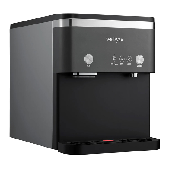
Summary of Contents for Wellsys WS15000
- Page 1 WS15000 Field Guide...
-
Page 2: Specifications
SPECIFICATIONS Model Name WS15000 Rated Voltage AC 120 V/60 Hz Allowable Pressure 14-100 psi (1~7kgf/cm Power 4.5 A (505 W) Consumption Weight 71.9 lbs (32.6kg) Refrigerant/Refrigerant Weight R-134a (1.48 oz ± 0.03 oz) Design Pressure 280 psig (19.3 bar) (High Side) Dimensions 360 W x 550D x 450 H (mm) (14.2 W x 21.7 D x 17.7 H (in)) - Page 3 DISPENSE BUTTONS ICE LED will be on when the ice is ready ICE LED to be served, and blink while dispensing. ICE DISPENSE BUTTON Push the button to dispense ice. LED UV LED will be on when the product LED UV LED LED UV is in operation (Yellow).
-
Page 4: Interior View
INTERIOR VIEW RIGHT SIDE & ICE BIN Ice Dispense Reservoir Evaporator Condenser Motor 91-3616-0 41-1911-1 Control Fans Board 41-2046-0 Hot Tank Compressor 91-3611-0 21-0864-0 Gear Motor Water-In 91-3608-0 Gear Motor Compressor Start Leak Detector Transmission Components Full Bin Sensors Cutter Auger 41-2058-0 21-0848-0 41-2059-0... - Page 5 INTERIOR VIEW TOP & BACK Water-In Cutter Auger Motor Full Bin Sensors Cutter Auger 41-2058-0 41-2059-0 21-0848-0 Hot Solenoid Condenser 41-1768-3 91-3616-0 Hot Tank Evaporator 91-3611-0 Dispense Gear Motor Auger 91-3608-0 21-0867-0 Ice Dispense Reservoir Motor Control Board Dispense Nozzle 41-1911-1 41-2046-0 91-3612-0...
-
Page 6: Level Sensor
INTERIOR VIEW WATER RESERVOIR Level Sensor Float Locking 41-1432-2 Clips... -
Page 7: Leak Detector
INTERIOR VIEW LEFT SIDE Full Bin Sensor Hot Solenoid Ice Dispense Damper Door Motor Motor 41-2058-0 41-1768-3 41-2059-0 41-1911-1 41-1285-0 Water-In UV Light Level Sensor Pump 41-1432-2 41-1405-0 Leak Detector... - Page 8 INTERIOR VIEW Damper Ice Dispense Ambient Door Motor Motor Dispense Reservoir Solenoid 41-1285-0 41-1285-0 Dispense Solenoid Level Sensor 41-1432-2 31-0577-1 Dispense Nozzle 91-3612-0 Control Board 41-2046-0 Safety Hot Tank Drain Resettable Hot Thermistor 91-3611-0 41-0308-0 Switch Thermal Cut-Off...
-
Page 9: Sediment Filter
INTERIOR VIEW FILTER ENCLOSURE Bio-Sure RO Membrane Plus Filter HF EX3R(P) HF EX4R(P) Precarbon Filter HF EX2(P) Post Carbon Sediment Filter Filter HF EX4R(P) HF EX1(P) Bulkhead ASO Valve Check Valve Bulkhead 803-504-20 900-503-00 WSUCV 803-504-20... -
Page 10: Wire Diagram
WIRE DIAGRAM... - Page 11 WATER FLOW MAP...
-
Page 12: Ice Making Process
ICE MAKING PROCESS The WS15000 will start making ice when the safety switch is depressed. Ice-full sensors and reservoir sensors will regulate the process. Water is drawn from either the RO, or from the reservoir below the ice bin. Melt water is returned to the reservoir where it is disinfected by UV light. -
Page 13: Installation
INSTALLATION 1. The ice machine must be installed indoors 2. Check water pressure, if over 70 psi, add a pressure regulator. 3. Place the ice machine so that it has five inches of clearance at the sides and rear of the unit, so it has proper ventilation. -
Page 14: Preventative Maintenance
PREVENTATIVE MAINTENANCE A. Open filter enclosure. Press this tab on both sides of the enclosure to remove the lid. Filter Change Regime: Pre-Sediment Filter (HF-EX1(P)) 1 year Pre-Carbon filter (HF-EX2(P)) 1 year Reverse Osmosis (HF-EX3R(P)) 2- 3 years Bio-Sure Plus RO (HF-EX4R(P)) 1 year TCR (HF-EX5(P)) 2 years... - Page 15 SANITIZING/DESCALING THE EVAPORATOR, WATER RESERVOIR AND ICE BIN This cleaning process must be followed every 6 months to a year depending NOTE: on unit condition and water quality. 1. Unplug unit from power and turn water off. 2. Remove front and top panels 3.
- Page 16 PREVENTATIVE MAINTENANCE 1. Drain the Unit 2. The ice bin and water reservoir drain ports are located behind the drip tray, while the hot tank drain is behind the front panel 3. Power down the unit and Insert supplied tube into desired drain port to drain unit Bin Drain Reservoir Drain Hot Drain...
- Page 17 ERROR CODES & BASIC TROUBLESHOOTING PROBLEM POSSIBLE CAUSE RESOLUTION Power Switch Is Switched To “Off” Turn the power switch to “on” position Position No Power From Outlet Check for voltage at outlet No Power If control board is receiving power, but not Control Board Unresponsive responding, then replace board Ball Valves Are Closed...
- Page 18 NO ICE TROUBLESHOOTING 1. Is there any Push Button LED blinking? A. ICE push Button is blinking when Auger Motor doesn’t operate properly. B. WATER push Button is blinking when there is no water has been supplied. 2. If there is no blinking, reset the system, by unplugging the power plug for 10 sec. 3.
-
Page 19: Parts Guide
PARTS GUIDE WETTED E LECT RON I C S 15000 - Sensor temperature (eva) 61-1908-0 15000 - Eps pad lower (white) 41-0308-0 2 Pedal system 61-1839-0 15000 - Eps auger (light gray) Foot switch XF-1D 15000 Ice and cold pedal 21-0848-0 15000 - Cutter auger WS120002PDLKIT...


Need help?
Do you have a question about the WS15000 and is the answer not in the manual?
Questions and answers