Table of Contents
Advertisement
Available languages
Available languages
Advertisement
Chapters
Table of Contents

Related Manuals for ENAR VET 1600


Summary of Contents for ENAR VET 1600
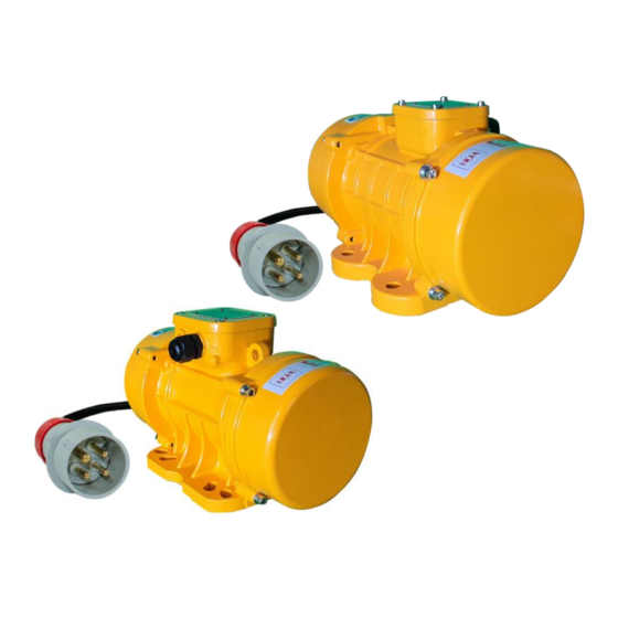
- Page 1 ENARCO, S.A. VIBRADORES EXTERNOS TRIFÁSICOS O MONOFÁSICOS SINGLE AND TRIPHASE EXTERNAL VIBRATORS VIBRATEURS EXTERNES TRIPHASÉE OU MONOPHASÉE DREIPHASIG ODER EINPHASIG RUTTLERMOTOR Manual de instrucciones Instruction manual Manuel d'instructions Gebrauchsanweisungen MX-410-2105...
-
Page 3: Table Of Contents
ÍNDICE PRÓLOGO CARACTERISTICAS REGLAS DE SEGURIDAD GENERALES Y ESPECIFICAS 3.1 AREA DE TRABAJO 3.2 SEGURIDAD ELÉCTRICA 3.3 SEGURIDAD PERSONAL 3.4 USO DE LA HERRAMIENTA Y CUIDADOS 3.5 SERVICIO 3.6 REGLAS DE SEGURIDAD ESPECÍFICAS 3.7 EQUIPOS DE PROTECCIÓN PERSONAL OPERACIÓN Y MANTENIMIENTO 4.1 PUESTA EN SERVICIO 4.2 CONEXION DEL MOTOR A LA RED ELECTRICA 4.3 CONEXION A TIERRA... -
Page 4: Prólogo
PRÓLOGO Agradecemos la confianza depositada en la marca ENAR. Para el máximo aprovechamiento de su equipo de vibración recomendamos que lea y entienda las normas de seguridad, mantenimiento y utilización recogidas en este manual de instrucciones. Las piezas defectuosas deben ser reemplazadas inmediatamente para evitar problemas mayores. -
Page 5: Caracteristicas
CARACTERISTICAS MODELO, MODEL, MODÈLE, MODEL 1600 POTENCIA, POWER, 1600 PUISSANCE, LEISTUNG TENSIÓN, VOLTAGE 3~220V/380V 50Hz 1~220V/50Hz TENSION, NENNSPANNUNG 3000 FUERZA CENTRÍFUGA CENTRIFUGE FORCE 0-1571 0-788 0-516 0-311 0-197 0-99 0-311 0-197 0-99 FORCE CENTRIFUGUE FLIEHKRAFT (Kg) PESO, WEIGHT, 52,6 21,1 16,3 10,5 10,5... -
Page 6: Reglas De Seguridad Generales Y Especificas
REGLAS DE SEGURIDAD GENERALES Y ESPECIFICAS ¡ATENCIÓN! LEA Y ENTIENDA TODAS LAS INSTRUCCIONES 3.1 AREA DE TRABAJO MANTENGA su zona de trabajo limpia y bien iluminada. NO HACER FUNCIONAR herramientas alimentadas en atmósferas explosivas, así como en presencia de líquidos inflamables, gases, o polvo. MANTENGA a espectadores, niños y visitantes alejados mientras este funcionando la herramienta. -
Page 7: Uso De La Herramienta Y Cuidados
NO SOBREPASE el límite de sus fuerzas. MANTÉNGASE bien alimentado y en equilibrio siempre. UTILICE equipo de seguridad. UTILICE siempre protección para los ojos. 3.4 USO DE LA HERRAMIENTA Y CUIDADOS UTILICE abrazaderas u otros elementos para asegurar y apoyar los elementos de trabajo en una plataforma estable. -
Page 8: Equipos De Protección Personal
Desconecte el vibrador de la red eléctrica antes de hacer cualquier servicio. Cuando conecte a un generador asegúrese que la tensión y frecuencia de salida es estable y correcta y es de la potencia adecuada, la tensión de alimentación del vibrador no deberá variar en +/- 5% de la marcada en la placa de características del motor. -
Page 9: Procedimiento Para Determinar La Sección Transversal Necesaria En Prolongación De Cable
4.5 PROCEDIMIENTO PARA DETERMINAR LA SECCION TRANSVERSAL NECESARIA EN PROLONGACION DE CABLE Se deberán hacer las siguientes comprobaciones y tomar la sección de cable mayor: La resistencia óhmica e inductiva del cable con una perdida de tensión permitida de un 5%, cos.phi = 0,8 mediante la curva de frecuencia y tensión. -
Page 10: Mantenimiento Periodico
4.6 INSPECCION Antes de iniciar los trabajos se deberá comprobar el correcto funcionamiento de todos los dispositivos de manejo y seguridad. Inspeccionar regularmente el buen estado de los cables de alimentación. Inspeccionar siempre la tensión de conexión. Cuando se comprueben defectos que hagan peligrar la manipulación segura, se debe suspender el trabajo y realizar el mantenimiento correspondiente. -
Page 11: Localización De Averias
LOCALIZACIÓN DE AVERIAS PROBLEMA CAUSA / SOLUCION El motor no funciona 1.- Verifique si hay corriente. 2.- Enchufe en mal estado. 3.- Interruptor defectuoso. El motor funciona 1.- Verifique la tensión de la fuerza eléctrica. lentamente y se 2.- Fase interrumpida. recalienta 3.- Compruebe las especificaciones del cable de prolongación 4.- Compruebe la tensión en el conmutador de tensión. -
Page 12: Modificación De La Fuerza Centrífuga
No tendrá ningún tipo de garantía cualquier equipo que haya sido previamente manipulado por personal no vinculado a ENARCO, S.A. NOTA: ENARCO, S.A. se reserva el derecho a modificar cualquier dato de este manual sin previo aviso MODIFICACIÓN DE LA FUERZA CENTRÍFUGA Tanto en los modelos VET como en los modelos VEM existe la posibilidad de ajustar la Fuerza centrífuga que es capaz de ofrecer el externo para así... - Page 13 • Tomando como referencia la muesca de la excéntrica, girar la excéntrica hasta la posición deseada. La escala muestra el porcentaje de la Fuerza centrífuga total que se obtiene. ATENCIÓN: en función de si el motor trabaja a 50Hz o 60Hz hay que usar escalas distintas. •...
- Page 14 • Aflojar la tuerca del eje. • Sacar el número de excéntricas necesarias y volverlas a montar giradas 180º. Porcentaje de la Fuerza Número de excéntricas por centrífuga total que se motor reduce por cada excéntrica que se gira 28.5 22.2 12+12 16.7...
- Page 15 TIPO 3 – Excéntricas macizas de media luna • Aflojar el tornillo de la excéntrica. • Tomando como referencia el plano medio de la excéntrica y girándola siempre en dirección contraria al prensaestopas del motor, girar la excéntrica hasta la posición deseada. La escala muestra el porcentaje de la Fuerza centrífuga total que se obtiene.
-
Page 16: Recomendaciones De Uso
RECOMENDACIONES DE USO 8.1 VIBRACION EXTERNA APLICACIONES DE LOS VIBRADORES DE EXTERNOS La vibración externa es aplicada en muchos campos, desde el vibrado de piezas prefabricadas de hormigón hasta el movimiento de material. A continuación no se va a entrar en detalle sobre el uso de los vibradores externos debido a la gran variedad de aplicaciones. - Page 17 A: Masa del molde/encofrado (kg) B: Masa del hormigón (kg) C: Constante dependiente de la consistencia del hormigón C=0.5 para muros, vigas. C=0.5 a 1 prefabricados horizontales C=1.5 para tuberías verticales. 2. Mesas vibrantes. Las mesas vibrantes se usan para la prefabricación de diferentes piezas de hormigón como vigas, pilotes, losas,..
- Page 18 3. Descarga de silos En la boca de descarga de los silos a menudo según las condiciones del material se apelmaza, de forma que se hace necesaria la instalación de vibradores. • Se colocan en la parte cónica de forma que produzcan aceleraciones de 1 a 2g, es decir de una fuerza centrífuga de 1 a 2 veces el peso de material de la tolva.
- Page 19 INDEX INTRODUCTION SPECIFICATIONS OF THE CONVERTERS USAGE CONDITIONS 3.1 WORK AREA 3.2 ELECTRICAL SAFETY 3.3 PERSONAL SAFETY 3.4 USE OF THE TOOL AND CARE 3.5 SERVICE 3.6 SPECIFIC SAFETY RULES 3.7 PERSONAL PROTECTIVE EQUIPMENT OPERATION AND MAINTENANCE 4.1 GETTING STARTED 4.2 ELECTRIC MOTOR CONECTION TO THE SYSTEM 4.3 EARTH CONNECTION 4.4 EXTENSION CABLES...
- Page 20 INTRODUCTION Thank you for trusting the ENAR brand For the maximum performance of the equipment, we recommend to read carefully the safety recommendations, maintenance, and usage listed in this manual Defective parts should be replaced immediately to avoid major problems.
- Page 21 SPECIFICATIONS OF THE CONVERTERS MODELO, MODEL, MODÈLE, MODEL 1600 POTENCIA, POWER, 1600 PUISSANCE, LEISTUNG TENSIÓN, VOLTAGE 3~220V/380V 50Hz 1~220V/50Hz TENSION, NENNSPANNUNG 3000 FUERZA CENTRÍFUGA CENTRIFUGE FORCE 0-1571 0-788 0-516 0-311 0-197 0-99 0-311 0-197 0-99 FORCE CENTRIFUGUE FLIEHKRAFT (Kg) PESO, WEIGHT, 52,6 21,1 16,3...
- Page 22 USAGE CONDITIONS WARNING! Read and understand all instruction. 3.1 WORK AREA KEEP your work area clean and well lit. Cluttered benches and dark areas invite accidents. DO NOT OPERATE power tools in explosive atmospheres, such as in the presence of flammable liquids, gases, or dust.
- Page 23 3.4 USE OF THE TOOL AND CARE USE clamps or other practical way to secure and support the work piece to a stable platform. DO NOT FORCE tool. USE the correct tool for your application. DO NOT USE tool if switch does not turn it on or off. DISCONNECT the plug from the power source before making any adjustments, changing accessories, or storing the tool.
- Page 24 WHEN FINISHING the job or when taking a break, the operator SHOULD UNPLUG, disconnect it from the electrical system, and have it placed in such a way that it should not fall or tip. During work with this system, the admissible noise of 70dB can be exceeded at some point.Proper protective equipment.
- Page 25 4.5 PROCEDURE TO DETERMINATE THE NECESSARY CROSS SECTION IN CABLE EXTENSION Do the following verifications and take the highest section of cable: The ohmic resistance and inductive resistance of the cable with the permitted loss of voltage of 5%, cosphi=0.8 trough the frequency and voltage curve I.e.
- Page 26 4.6 INSPECTION 1. Before starting the job, check the correct working of all handling and safety devices. 2. Inspect regularly the good conditions of the feeding cables. 3. Inspect regularly the connection voltage. 4. If defects are found in the safety devices or other defects which could reduce the safe handling of the equipment, notify immediately the proper responsible person.
- Page 27 LOCATING MALFUNCTIONS PROBLEM CAUSE/SOLUTION The unit is not working 1.- Check if there is current. 2.- Plug in bad condition. 3.- Defective switch. The motor works slowly 1.- Check the tension of the electric power. and it overheats 2.- Phase interrupted. 3.- Check the specifications of the extension cable 4.- Check the voltage at the voltage switch.
- Page 28 MODIFICATION OF CENTRIFUGAL FORCE Both in the VET models and in the VEM models exist the possibility of adjusting the centrifugal force that the external vibrator is capable of offering in order to be able to adapt to different needs. To achieve this adjustment, it is necessary to modify the eccentrics of the motor through a few simple steps: 1.
- Page 29 • Tighten the eccentric screw. TYPE 2 - Extractable eccentrics. • Loosen the axle nut. • Remove the number of eccentrics required and reassemble them turned 180º. MONO-PHASE AND THREE-PHASE EXTERNAL VIBRATORS VET VEM...
- Page 30 Percentage of total Number of eccentrics per Centrifugal Force that is motor reduced by each eccentric that is turned 28.5 22.2 12+12 16.7 • Put the nut back on the shaft. TYPE 3 - Solid crescent eccentrics MONO-PHASE AND THREE-PHASE EXTERNAL VIBRATORS VET VEM...
- Page 31 • Loosen the eccentric screw. • Taking the median plane of the eccentric as a reference and always turning it in the opposite direction to the motor gland, turn the eccentric to the desired position. The scale shows the percentage of the total Centrifugal Force that is obtained. ATTENTION: If the motor works at 50Hz or 60Hz you have to use different scales.
- Page 32 • As a general principle this means choosing vibrators whose centrifugal force (in Kg) is 1.5 times the weight of the mould. • It is recommended to use a greater number of vibrators distributed over the mould even though the centrifugal force could be achieved with a lower number. •...
- Page 33 Mould attached to vibrating table: F = C(D+B+0.2A) A: Weight of mould / form (kg) B: Weight of concrete (kg) C: Constance dependent upon the consistency of the concrete and the rigidity of the mould. Its value lies between 2 and 4. D: Mass of vibrating part, including vibrators (kg) 3.
- Page 35 INDICE PROLOGUE CARACTERISTIQUES DU MOTEUR ELECTRIQUE REGLES DE SECURITE GENERALES ET PARTICULIERES 3.1 AIRE DE TRAVAIL 3.2 SÉCURITÉ ÉLECTRIQUE 3.3 SÉCURITÉ DES PERSONNES 3.4 UTILISATION ET ENTRETIEN DES OUTILS 3.5 RÉPARATION 3.6 RÈGLES DE SÉCURITÉ PARTICULIERES 3.7 EQUIPMENTS DE PROTECTION INDIVIDUEL MANIPULATION ET ENTRETIEN 4.1 MISE EN SERVICE 4.2 CONNEXION DU MOTEUR ELECTRIQUE AU RESEAU...
-
Page 36: Prologue
Nous vous remercions de la confiance que vous avez déposé en la marque ENAR. Pour profiter de votre appareil ENAR , nous vous recommandons de bien vouloir lire attentivement les recommandations de sécurité, entretien et utilisation que regroupe ce manuel d'instructions. -
Page 37: Caracteristiques Du Moteur Electrique
CARACTERISTIQUES DU MOTEUR ELECTRIQUE MODELO, MODEL, MODÈLE, MODEL 1600 POTENCIA, POWER, 1600 PUISSANCE, LEISTUNG TENSIÓN, VOLTAGE 3~220V/380V 50Hz 1~220V/50Hz TENSION, NENNSPANNUNG 3000 FUERZA CENTRÍFUGA CENTRIFUGE FORCE 0-1571 0-788 0-516 0-311 0-197 0-99 0-311 0-197 0-99 FORCE CENTRIFUGUE FLIEHKRAFT (Kg) PESO, WEIGHT, 52,6 21,1 16,3... -
Page 38: Regles De Securite Generales Et Particulieres
REGLES DE SECURITE GENERALES ET PARTICULIERES AVERTISSEMENT! Vous devez lire et comprendre toutes les instructions 3.1 AIRE DE TRAVAIL VEILLEZ à ce que l'aire de travail soit prope et bien éclairée N'UTILISEZ pas d'outils électriques dans une atmosphère explosive, par exemple en présence de liquides, de gaz ou de poussières inflammables. -
Page 39: Utilisation Et Entretien Des Outils
AVANT DE BRANCHER l'outil, assurez-vous que son interrupteur est sur arrêt (0) ENLEVEZ les clés de réglage ou de serrage avant de démarrer l'outil NE VOUS PENCHEZ pas trop en avant MAINTENEZ un bon appui et restez en équilibre en tous temps UTILISEZ des accessoires de sécurité... -
Page 40: Equipments De Protection Individuel
NE PAS LAISSER qu’un personnel inexpérimenté ou non capacité manipule le vibreur ou ses connexions. MAINTENIR le vibreur propre et sec. VÉRIFIER que le câblage est de section adéquate et qu’il est en parfait état. AVANT DE MANIPULER le moteur, l’arrêter avec l’interrupteur et débrancher la prise du réseau. LORSQUE L’ON CONNECTE le vibreur à... -
Page 41: Cables Procede Pour Determiner L'aire De Section Des Cables Derallonge
N'utilisez pas de câbles endommagés ou usés. Eviter d’écraser les câbles ou de faire passer de lourdes charges dessus. Pour déterminer la section transversale, suivez le point 4.5. 4.5 CABLES PROCEDE POUR DETERMINER L'AIRE DE SECTION DES CABLES DE RALLONGE Il faudra faire les vérifications suivantes et mesuser l'aire de section du plus gros câble. -
Page 42: Inspection
4.6 INSPECTION 1. Avant de commencer à travailler, vérifier que tous les dispositifs d'utilisation et de sécurité fonctionnent bien. 2. Vérifier régulièrement le bon état des câbles d'alimentation. 3. Toujours vérifier la tension de connexion. 4. Lorsque un défaut est détecté, suspendre le travail et procéder immédiatement à la réparation dece(s) défauts. -
Page 43: Localisation Des Pannes
LOCALISATION DES PANNES PROBLEME CAUSE / SOLUTION Le moteur ne 1.- Vérifier s'il y a du courant. fonctionne pas 2.- Prise(s) en mauvais état. 3.- Interrupteur defectueux. Le moteur fonctionne 1.- Vérifier la tension d'alimentation. lentement et chauffe 2.- Une phase interrompue 3.- Vérifier les caractéristiques du câble de rallonge. -
Page 44: Modification De La Force Centrifuge
Tout appareil qui aurait été manipulé par un réparateur ou un personnel non agrée par ENARCO, S.A ne pourra être garanti. REMARQUE: ENARCO, S.A. se réserve le droit de modifier toute information contenue dans ce manuel sans préavis MODIFICATION DE LA FORCE CENTRIFUGE Tant dans les modèles VET que dans les modèles VEM, il y a la possibilité... - Page 45 ATTENTION : selon que le moteur fonctionne à 50 Hz ou à 60 Hz, différentes échelles doivent être utilisées. • Resserrer la vis excentrique. b. TYPE 2 - Excentriques extractibles. • Desserrez l'écrou d'axe. • Retirer le nombre d'excentriques requis et les remonter à 180º. VIBRATEURS EXTERNES TRIPHASÉE OU MONOPHASÉE VET VEM...
- Page 46 Pourcentage de la Forçe Nombre d’exentriques centrifuge total qui se reduit pour chaque par moteur excentrique qui se tourne 28.5 22.2 12+12 16.7 • Remettez l'écrou sur l'axe. c. TYPE 3 - Excentriques en demi lune . VIBRATEURS EXTERNES TRIPHASÉE OU MONOPHASÉE VET VEM...
-
Page 47: Recommandations D'utilisation
Desserrer la vis excentrique. • En prenant comme référence le plan médian de l'excentrique et en le tournant toujours dans le sens inverse du presse-étoupe, tourner l'excentrique dans la position souhaitée. L'échelle indique le pourcentage de la force centrifuge totale qui est obtenue. ATTENTION : selon que le moteur fonctionne à... - Page 48 • Les vibrateurs sont répartis sur la surface du moule de manière à obtenir une accélération de 1,5 g. • Les vibreurs à force centrifuge sont choisis pour obtenir cette accélération. • De manière générale, on choisit des vibreurs dont la force centrifuge en kg est 1,5 fois le poids du moule •...
- Page 49 • Des accélérations de 2 à 4g doivent être appliquées à la table en fonction de l'application • Placer un seul vibrateur au centre de gravité de l'ensemble vibrant produit une vibration circulaire. • Si deux vibrateurs identiques sont placés, à la même distance du centre de gravité, avec un sens de rotation différent, ils fournissent un mouvement vibratoire linéaire.
- Page 51 INHALTSVERZEICHNIS VORWORT DATEN DER PATSCHEN EINSATZVORAUSSETZUNGEN 3.1 ARBEITSPLATZ 3.2 ELEKTRISCHE SPEISUNG 3.3 PERSÖNLICHE SICHERHEIT 3.4 ANWENDUNG UND WARTUNG 3.5 WARTUNG 3.6 BESONDERE SICHERHEITSVORSCHRIFTEN 3.7 PERSÖNLICHE SCHUTZAUSRÜSTUNG BETRIEB UNE WARTUNG 4.1 INBETRIEBNAHME 4.2 ERDUNG 4.3 VERLÄNGERUNGSKABEL 4.4 ÜBERPRÜFUNG 4.5 REGELMÄSSIGEWARTUNG 4.6 LAGERUNG 4.7 TRANSPORT FEHLERSUCHE SCHALSCHEMA ANWEISUNGEN FÜR DIE BESTELLUNG VON ERSATZTEILEN...
-
Page 52: Vorwort
Wir empfehlen Ihnen, die Sicherheits- , Instandhaltungs- und Anwendungsvorschriften in diesem Handbuch zu lesen, damit Sie Ihre ENAR - Anlage voll ausnützen können. Beschädigte Teile müssen umgehend ausgewechselt werden, um größere Probleme zu vermeiden. Die Einsatzbereiche der Maschine nehmen zu, wenn Sie den Anweisungen dieses Handbuchs folgen. -
Page 53: Daten Der Patschen
DATEN DER PATSCHEN MODELO, MODEL, MODÈLE, MODEL 1600 POTENCIA, POWER, 1600 PUISSANCE, LEISTUNG TENSIÓN, VOLTAGE 3~220V/380V 50Hz 1~220V/50Hz TENSION, NENNSPANNUNG 3000 FUERZA CENTRÍFUGA CENTRIFUGE FORCE 0-1571 0-788 0-516 0-311 0-197 0-99 0-311 0-197 0-99 FORCE CENTRIFUGUE FLIEHKRAFT (Kg) PESO, WEIGHT, 52,6 21,1 16,3... -
Page 54: Einsatzvoraussetzungen
EINSATZVORAUSSETZUNGEN ACHTUNG! Bitte lesen und verstehen Sie jede Anweisung. 3.1 ARBEITSPLATZ BEWAHREN ihrer Arbeitsplatz beleuchtet und gereinigt. Schmutz und Dunkel verursachen Unfälle. NICHT ANWENDEN Geräte in explosiven Atmosphären, wie Flüssigkeiten, Gasen, oder Staub. Die Geräte können Funken und Explosionen versursachen. Die Maschine kann nur durch geschultes Personal über 18 Jahren, die Betriebsanleitung gelesen und verstanden haben verwendet werden. -
Page 55: Anwendung Und Wartung
VERMEIDEN Sie eine überanwendung, nehmen Sie Pausen , für Sie und das Gerät. VERMEIDEN anormale Körperhalterung und versichern Sie die Fusshaltung, damit werden SIe die Kontrolle in unerwarteten Lagen nicht lösen. VERWENDEN Sie die Sicherheitsausstattungen . Immer AUGENSCHUTZ ANWENDEN. Staub Schutz, Sicherheitsschuhe, Helm, Or schutz mussen verwendet werden. -
Page 56: Persönliche Schutzausrüstung
Schliessen Sie die Biegsame Welle nicht an den laufenden Motor. Manipulieren Sie bei laufendem Motor oder ohne Übersetzung am laufenden Motor herum. Arbeiten Sie bei beschädtigter Welle (Übersetzungsgetriebe) oder Flasche (Rüttellanze) mit dem Motor.Er würde Sonst Heisslaufen. Nicht arbeiten, wenn das Kunststoffgehäuse des Motors kaputt ist. Unbefugtem und Unerfahrenem Personal ist das Bedienen des Motors oder seiner Anschlüsse zu untersagen. -
Page 57: Verlängerungskabel
4.3 VERLÄNGERUNGSKABEL Nur dreiphasige verlängerungskabel verwenden, bei denen sowohl Stecker als auch Steckdose mit drei Leitern ausgerüstet sind und in die der am Motor angebrachte Stecker passt. Keine beschädigten oder abgenützten Kabel verwenden . Keine schweren Lasten über die Kabel ziehen. Zur Ermittlung desw Querschnitts folgendermassen verfahren : VERFAHREN ZUR BESTIMMUNG DES BEI DER KABELVERLÄNGERUNG NOTWENDIGEN QUERSCHNITTS... -
Page 58: Überprüfung
Die zulässige Erhitzung des Kabels nach VDE (Tabelle für den mindesterforderlichen Querschnitt): z. B. Für 10 A beträgt der Querschnitt, laut Tabelle für 15 A oder weniger, 1 mm. Mindestquerschnitte nach VDE – Norm Leitung Höchst belastung Sicherung höchstens 10/3-16/1- Also beträgt der gewählte Querschnitt 4 mm, von den zwei Tests stets den größeren Querschnitt wählen. -
Page 59: Lagerung
Nach Service- und Wartungsarbeiten alle Teile der Sicherheitsvorrichtungen wieder richtig zusammenbauen. Ungefähr alle 40 Betriebsstunden die Halterungsschrauben am Gehäuse überprüfen. Je nach Einsatzbedingungen die Maschine alle 12 Monate, oder öfter, in einer Vertragswerkstatt überholen lassen. 4.6 LAGERUNG Den Umformer stets an einem sauberen, trockenen und geschützten Ort aufbewahren, wenn er für eine längere Zeit nicht benutzt werden soll. -
Page 60: Anweisungen Für Die Bestellung Von Ersatzteilen
ANWEISUNGEN FÜR DIE BESTELLUNG VON ERSATZTEILEN 6.1 ANWEISUNGEN FÜR DIE BESTELLUNG VON ERSATZTEILEN allen Ersatzteilbestellungen muß TEILELISTE AUFGEFÜHRTE BESTELLNUMMER DES ERSATZTEILS angegeben werden. Es wird empfohlen, ebenfalls DIE FABRIKATIONSNUMMER DER MASCHINE anzugeben. Die Kennplakette mit den Serien- und Modellnummern befindet sich auf der Oberseite des Kunststoffgehäuses des Motors, beim Übersetzungsgetriebe und der Lanze steht die Nummer außen. -
Page 61: Änderung Der Zentrifugalkraft
ÄNDERUNG DER ZENTRIFUGALKRAFT Sowohl bei den VET-Modellen als auch bei den VEM-Modellen besteht die Möglichkeit, die Fliehkraft, die der Externe aufbringen kann, anzupassen, um sich an unterschiedliche Bedürfnisse anpassen zu können. Um diese Einstellung zu erreichen, ist es notwendig, die Exzenter des Motors in wenigen einfachen Schritten zu ändern: 1. - Page 62 • Exzenterschraube wieder festziehen. TYP 2 - Ausziehbare Exzenter. • Achsmutter lösen. • Die benötigte Anzahl Exzenter entfernen und um 180° gedreht wieder montieren. DREIPHASIG ODER EINPHASIG RUTTLERMOTOR VET VEM...
- Page 63 Prozentsatz der gesamten Zentrifugalkraft, der durch Anzahl Exzenter pro Motor jeden gedrehten Exzenter reduziert wird 28.5 22.2 12+12 16.7 • Setzen Sie die Mutter wieder auf die Welle. DREIPHASIG ODER EINPHASIG RUTTLERMOTOR VET VEM...
- Page 64 TYP 3 - Vollhalbmond-Exzenter. • Lösen Sie die Exzenterschraube. • Nehmen Sie die Mittelebene des Exzenters als Referenz und drehen Sie ihn immer in die entgegengesetzte Richtung zur Motorstopfbuchse, und drehen Sie den Exzenter in die gewünschte Position. Die Skala zeigt den erhaltenen Prozentsatz der gesamten Zentrifugalkraft an.
-
Page 65: Anwendungsempfehlungen
ANWENDUNGSEMPFEHLUNGEN 8.1 EXTERNE VIBRATION EXTERNE VIBRATOR-ANWENDUNGEN Externe Vibrationen werden in vielen Bereichen angewendet, von vibrierenden Betonfertigteilen bis hin zu bewegtem Material. Auf den Einsatz von Außenrüttlern wird aufgrund der vielfältigen Einsatzmöglichkeiten im Folgenden nicht näher eingegangen. Es werden nur einige kurze Bemerkungen zu den gängigsten Anwendungen gemacht: 1.- Vibrationsformen. - Page 66 C: Konstante abhängig von der Konsistenz des Betons. C= 0,5 für Wände, Balken. C= 0,5 bis 1 horizontale Fertigteile. C= 1,5 für vertikale Rohre. 2. Lebendige Tische. Die Rütteltische werden zur Vorfertigung unterschiedlicher Betonteile wie Balken, Pfähle, Platten, .. eingesetzt. Sie können auch zum Verdichten von körnigen Materialien wie Gießformen und anderen pulverförmigen Materialien eingesetzt werden.
- Page 67 FOR ANY REQUIREMENT ABOUT THE PART LIST OF OUR MACHINES CONSULT OUR WEB PAGE. POUR CONSULTER TOUS LES RENSEIGNEMENTS DES PIÈCES DETACHEES OU LA LISTE DE NOS MACHINES VOIR NOTRE SITE. UM DIE VERSCHIEDENE EXPLOSIONSZEICHNUNGEN SO WIE DIE ERSATZTEILLISTEN EINZUSEHEN, BESUCHEN SIE BITTE UNSERE INTERNET-SEITE. www.enar.es...
- Page 68 Technical documentation responsible ~ Responsable of the Documentation Technnique ~ zuständigen technishen Dokumentation Zaragoza, 01.10.2011 David Gascón General Manager ENARCO,S.A. ENARCO, S.A. Tfno. (34) 976 464 090 C/ Burtina 16 e-mail: enar@enar.es (34) 976 464 091 Plataforma logística PLAZA Web: http://www.enar.es (34) 976 471 470 50197 ZARAGOZA SPAIN...
Need help?
Do you have a question about the VET 1600 and is the answer not in the manual?
Questions and answers