
Related Manuals for Paradox Hellas S.A. DEVELOPED Neon 2

Summary of Contents for Paradox Hellas S.A. DEVELOPED Neon 2
- Page 1 Installation and Operation Manual Conventional Fire Alarm Control Panel Version: 1 Revision: 4...
- Page 2 Declaration of Conformity IMPORTANT INFORMATION Limitation of liability Fire alarm control panel NEON is certified from EVPU (Noti- fied body No. 1293) according to European Regulation CPR It is mandatory for the NEON panel to be installed in ac- 305/2011 with certification number Νο.1293-CPR-0604 of June cordance with this manual, applicable codes, and the in- 27, 2018.
-
Page 3: Table Of Contents
TABLE OF CONTENTS 1. Components Description 9. Power Supply 1.1 Neon Panel - Components identification - Cabinet 9.1 Power Consumption inside view 9.2 Recommended batteries 1.2 Neon Panel - Wiring diagram and information 10. Wiring Connections of Inputs / Outputs 13 2. -
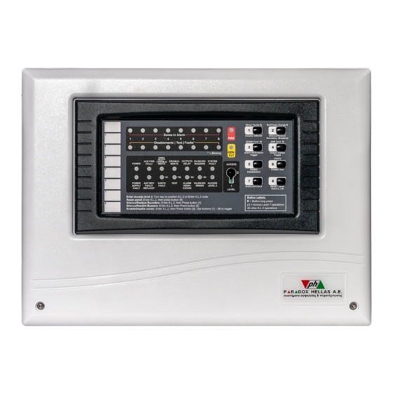
Page 4: Components Description
1. Components Description 1.1 Neon Panel - Components identification - Cabinet inside view 1. Connector for communication board: Connects to 17. JP204: NO/NC dry contacts operated during reset. the TCP/IP module (optional). 18. ‘AUX R’: Auxiliary power output interrupted during re- 2. -
Page 5: Neon Panel - Wiring Diagram And Information
1.2 Neon Panel - Wiring diagram and information Battery Connection Terminal Hardware Reset Button Fuse 1.6A / 250V Fast blow Fuse 5A / 250V Slow blow Fuse 1A / 250V Slow blow Mains Power Supply 230 V AC / 50-60Hz / 2.5A Signaling Devices Fire Relay Output Day/Night... -
Page 6: Typing Conventions And Abbreviations
2. Typing conventions and abbreviations Cabinet dimensions Throughout this manual specific symbols and character types have special meaning. The following list summarizes the typing conventions: • [Button]: A Keypad button that can be pressed. • *Indicator*: A visual indicator that may be lit or not. e.g. -
Page 7: Access Level 1 Operations
layed from” Zones (F1-F8), Pre-alarm Relay While key [4] is kept pressed the panel shows the configu- ration related to the 4 Siren (relay) outputs: • Fault indicators (FL1-FL8): Zones that will be de- layed if triggered by an alarm are blinking. •... -
Page 8: Indications
Any new alarm event will automatically cancel the silence. If any zone is in test mode, the *TEST* indicator is illuminated. If no sounders are active, the silence operation will only momentarily activate the corresponding indicator. Key [7]: EVACUATION (Long Press) Bell / Class change (Long Press) This operation requires Access level 2 if SW-C-8 is set While key [2] is kept pressed, the Sounders normally used... -
Page 9: Siren Faults / Disablements Indication
• Battery missing: Indicator steady ON. • ON: The system has programmed and active delays to outputs. • Battery wiring open circuit: Indicator steady ON. • Battery not able to charge (low voltage): Indicator steady • BLINKING: The system has programmed delays to outputs but they are currently disabled with an Access •... -
Page 10: General Fault Indication (General Fault)
5.3.16 General Fault indication (General Fault) Alarm signal. Only then will the General Alarm condition be activated. To prevent the First Alarm signal from causing a GENERAL FAULT, indicates a problem in the system. It General Alarm, it must originate from an intellizone. turns ON (steady ON) in case of:... -
Page 11: System Setup - Zone Assignment - Intellizone
This input may also be used with a manual external switch, • A group of outputs (relays) that will activate with de- to provide an easier operation of the “Alarm Verification lay if the Alarm is triggered by a “Delayed zone”(called Disable/enable”... -
Page 12: Micro Switches Sw-A
board of the panel there are three (3) sets of micro switch- connected to the detectors that are installed in the pro- es modules SW-A to SW-C. Every module consists of 8 tected area. A common practice is to install different types micro switches No.1 to No.8 as shown on Figure... -
Page 13: H/W Reset Button
Table 8. Micro switches SW-C 8.4 H/W Reset button The PCB RESET button (Item 5, page 4) should only be used by the installer. It is used to restart the microcontroller or to make effective any changes made via the micro dip switches. - Page 14 ZONES DESCRIPTION nation, the EOL devices must be 22uF electrolytic capaci- tors (25V DC). The Active EOL (AEOL) method of detection,recognizes Zone 1:_______________________________________ the removal of a single detector while the rest of the detec- tors down the zone remain in operation (alarms are recog- Zone 2:_______________________________________ nized).
-
Page 15: Appendix A: Panel Specifications
Panel Specifications Appendix A: Neon 2 Neon 4 Neon 8 Number of zones Maximum number of detectors per zone Notification appliances outputs (e.g. sirens) Notification appliances current 4 x 400mA (total maximum current 1Amp) Mains Power 230V AC 50/60Hz Zones input voltage (with EOL & AEOL) 16 to 21 V Maximum input power 100 VA max input power (0.5 Amp) - Page 16 Document Part Number: NEON-PI01, CPR version 1, revision 4 - 12/2018...
Need help?
Do you have a question about the DEVELOPED Neon 2 and is the answer not in the manual?
Questions and answers