Table of Contents
Advertisement
Available languages
Available languages
Quick Links
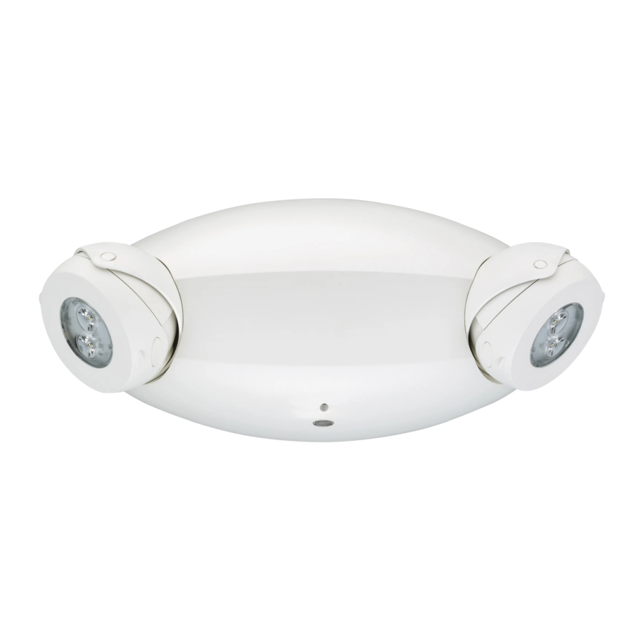
ELM4L & ELM6L
EMERGENCY LIGHTING UNIT
Installation and wiring ................................................................................... P. 2-3
Testing and maintenance ..............................................................................P. 4-5
NOTE: Product versions that are certified in the CA Title 20 Appliance Efficiency Database are marked
BC on the product label.
!
WARNING:
FAILURE TO FOLLOW THESE INSTRUCTIONS AND WARNINGS MAY RESULT IN DEATH, SERIOUS INJURY OR
SIGNIFICANT PROPERTY DAMAGE
maintaining this equipment. These instructions do not attempt to cover all installation and maintenance situations. If you do not understand
these instructions or additional information is required, contact Holophane.
!
WARNING: RISK OF ELECTRIC SHOCK – NEVER CONNECT TO, DISCONNECT FROM OR SERVICE WHILE EQUIPMENT IS
!
ENERGIZED
.
WARNING:
DO NOT USE ABRASIVE MATERIALS OR SOLVENTS. USE OF THESE SUBSTANCES MAY DAMAGE FIXTURE,
WHICH MAY RESULT IN PERSONAL INJURY.
!
WARNING
: RISK OF PERSONAL INJURY – This product may have sharp edges. Wear gloves to prevent cuts or abrasions when removing
!
from carton, handling, installing and maintaining this product.
WARNING:
The battery used in this device may present a risk of fire or chemical burn if mistreated. Temperature range 50°F -104°F (10°C -40°C).
Do not disassemble, heat above 70°C (158°F), or incinerate. Replace battery only as directed on the battery label and page 5 of these instructions.
Use of unauthorized battery voids warranty and UL listing of this product and may present a risk of fire or explosion.
•Disconnect A.C. power before servicing.
•All servicing should be performed by qualified personnel.
•Consult your local building code for approved wiring and installation.
•Do not use outdoors unless used with Acuity Brands accessories appropriate to the application.
•Do not mount near gas or electric heater.
•Equipment should be mounted in locations and at heights where it will not readily be subjected to tampering by unauthorized personnel.
•The use of accessory equipment not recommended by the manufacturer may cause an unsafe condition.
•Do not use this equipment for other than intended use.
AND DELIVER TO OWNER AFTER INSTALLATION
Remote test option
IMPORTANT SAFEGUARDS
When using electrical equipment, basic safety precautions
should always be followed, including the following:
READ AND FOLLOW ALL SAFETY INSTRUCTIONS
- For your protection, read and follow these warnings and instructions carefully before installing or
SAVE THESE INSTRUCTIONS
"TEST" button / Status I
ndicator
Press latches to disengage
housing from mounting plate
Advertisement
Table of Contents

Related Manuals for Quantum ELM4L


Summary of Contents for Quantum ELM4L
- Page 1 ELM4L & ELM6L EMERGENCY LIGHTING UNIT Installation and wiring …………………..…………..…………………………………… P. 2-3 Testing and maintenance ………...…………………………………………………………P. 4-5 NOTE: Product versions that are certified in the CA Title 20 Appliance Efficiency Database are marked BC on the product label. Remote test option “TEST”...
-
Page 2: Installation And Wiring
NOTE: To meet the minimum illumination requirements of NFPA 101 (current Life Safety Code), the maximum mounting height from ground of ELM4L is 26.3 feet, and of ELM6L is 32.9 feet. NOTE: Do not connect battery or power unit until remote units (if applicable) are fully connected and wires are isolated from other potentials (i.e. -
Page 3: Final Assembly
INSTALLATION and WIRING (CONTINUED) page 3 FINAL ASSEMBLY Federal Communications Connect the polarized battery plug to Housing attachment to mounting plate: Commission (FCC) Requirements: the charger board. Make certain that Make certain all wires and connectors are This device complies with FCC Title the battery cable is routed to avoid routed to avoid interference with other 47, Part 15, Subpart B. -
Page 4: Testing And Maintenance
TESTING and MAINTENANCE page 4 IMPORTANT BATTERY INFORMATION: NOTE: Emergency lighting systems should be tested in Batteries are perishable items. For best results, it is accordance with NFPA 101 or as often as local codes recommended that the batteries receive an initial charge within require, to ascertain that all components are operational. -
Page 5: Battery Replacement
TESTING and MAINTENANCE page 5 BATTERY REPLACEMENT Unit features and battery details shown may vary. See also “Battery Connection”, page 3. Disconnect battery from charger board. Replace battery, secure the strap Re-assemble the unit (see also snugly, and reconnect to the charger step 5, page 3). -
Page 6: Maintenance
MAINTENANCE page 6 CLSR MODULE REPLACEMENT Disconnect the battery connector To replace the CLSR module, With the unit oriented as shown from charger board and remove disconnect the module from below, flex the left PCB guide for charger board and replace the battery (see page 5 for the charger board outward to additional information) -
Page 7: Medidas De Seguridad Importantes
ELM4L y ELM6L UNIDAD DE ILUMINACIÓN DE EMERGENCIA Instalación y cableado …………………..…………..…………………………………… Pág. 2-3 Prueba y mantenimiento ………...………………………………………………………….. Pág. 4-5 NOTA: Las versiones de producto que cumplen con el Título 20 de California están marcadas con “BC” en la etiqueta del producto. -
Page 8: Instalación Y Cableado
NOTA: Para cumplir con los requisitos mínimos de iluminación de la NFPA 101 (Código actual de Seguridad Humana), la máxima altura de montaje de ELM4L desde el suelo es de 26.3 pies, y la máxima altura de montaje de ELM6L desde el suelo es de 32.9 pies. -
Page 9: Montaje Final
INSTALACIÓN Y CABLEADO (CONTINUACIÓN) página 3 MONTAJE FINAL Requisitos de la Comisión Federal Conecte el enchufe de la batería Accesorios de la carcasa para la placa de de Comunicaciones (FCC): polarizado a la placa del cargador. montaje: Asegúrese de que todos los cables y los conectores Este dispositivo cumple con el Título Asegúrese de verificar el recorrido del sigan una ruta para evitar la interferencia con otros... - Page 10 PRUEBA y MANTENIMIENTO página 4 NOTA: Los sistemas de iluminación de emergencia deben ser INFORMACIÓN IMPORTANTE SOBRE LAS BATERÍAS: probados de acuerdo con la norma NFPA 101 o con la Las baterías son productos perecederos. Para obtener mejores regularidad que exijan los códigos locales, para verificar que resultados, se recomienda que las baterías reciban una carga inicial todos los componentes sean operativos.
-
Page 11: Reemplazo De La Batería
PRUEBA y MANTENIMIENTO página 5 REEMPLAZO DE LA BATERÍA: Las características de la unidad y los detalles de la batería que se muestran pueden variar. Vea también “Conexiones de batería” en la página 3. Desconecte la batería del cargador Reemplace la batería, asegure bien la Vuelva a ensamblar la unidad (consulte cinta y vuelva a conectarla a la placa también el paso 5 en la página 3). -
Page 12: Mantenimiento
MANTENIMIENTO página 6 REEMPLAZO DEL MÓDULO CLSR Con la unidad orientada como se Desconecte el conector de la Para reemplazar el módulo CLSR, muestra a continuación, flexione batería del tablero del cargador y desconecte el módulo de la placa del cargador y reemplácelo (la hacia fuera la guía de la PCB extraiga la batería (consulte la página 5 para obtener información...
Need help?
Do you have a question about the ELM4L and is the answer not in the manual?
Questions and answers