Table of Contents
Advertisement
Quick Links
COND SGA-A & COND SGA-D
1. INTRODUCTION ......................................................................................................................................................................................................... 2
2. INSTALLING THE COND SGA/A & COND SGA/D .................................................................................................................................................... 2
2.1. Pre Installation.................................................................................................................................................................................................... 2
2.2. Dimensions......................................................................................................................................................................................................... 3
2.3. Cabling................................................................................................................................................................................................................ 3
2.3.1. Power Connection ..................................................................................................................................................................................... 3
2.3.2. Input (Sensor) Connections....................................................................................................................................................................... 4
2.3.3. Output Connections................................................................................................................................................................................... 5
3. SWITCH SETTINGS ................................................................................................................................................................................................... 6
3.1. Output Settings - Switch 4 .................................................................................................................................................................................. 6
3.1.1. Output Option ............................................................................................................................................................................................ 6
3.1.2. Switch 4 ..................................................................................................................................................................................................... 6
3.1.3. Example :- 0-10 Volt output with no filter required. ................................................................................................................................... 7
3.2. Output Filter Settings -Switch 3 ......................................................................................................................................................................... 7
3.2.1. Switch 3 ..................................................................................................................................................................................................... 7
3.2.2. Example : The Switch Settings for a cut-off frequency of 50 Hz setting is illustrated below..................................................................... 8
3.3. Output Current Mode and Input Filter Settings - Jumpers JP1, JP2 & JP3....................................................................................................... 8
3.4. Span (Gain) Setting Switch 1 ............................................................................................................................................................................. 8
3.4.1. SW1 ........................................................................................................................................................................................................... 9
3.4.2. Example : A strain gauge has a sensitivity of 2.809 mV /V ..................................................................................................................... 10
3.5. Shunt Calibration Switch SW1/8....................................................................................................................................................................... 10
3.6. Zero (Offset) Setting Switch SW2..................................................................................................................................................................... 10
3.6.1. Example :An installation has a tare of 15 kg with a 200kg strain gauge which gives an output of 6.37mV/V at 10V excitation............. 11
4. CALIBRATION........................................................................................................................................................................................................... 11
4.1. Output............................................................................................................................................................................................................... 11
4.2. Zero Offset........................................................................................................................................................................................................ 11
4.3. Sensitivity.......................................................................................................................................................................................................... 11
4.4. Calibration Connections using mV Source....................................................................................................................................................... 12
5. TROUBLESHOOTING .............................................................................................................................................................................................. 13
5.1. No output .......................................................................................................................................................................................................... 13
5.1.1. For voltage output.................................................................................................................................................................................... 13
5.1.2. For current output .................................................................................................................................................................................... 13
5.2. Low Output ....................................................................................................................................................................................................... 13
5.3. High output ....................................................................................................................................................................................................... 14
5.4. Unstable Output................................................................................................................................................................................................ 14
5.4.1. Poor Installation ....................................................................................................................................................................................... 14
5.4.2. Noisy Environment................................................................................................................................................................................... 14
5.5. Calibration......................................................................................................................................................................................................... 14
5.6. Fine Span (Gain) and Zero (Offset) Adjustment Problems .............................................................................................................................. 14
6. PRODUCT CARE...................................................................................................................................................................................................... 15
7. GLOSSARY............................................................................................................................................................................................................... 15
8. SPECIFICATIONS FOR COND SGA/A & COND SGA/D LOAD CELL AMPLIFIERS ............................................................................................. 18
8.1. Parameter......................................................................................................................................................................................................... 18
8.2. Output options .................................................................................................................................................................................................. 19
8.3. Connections...................................................................................................................................................................................................... 19
8.4. Enclosure.......................................................................................................................................................................................................... 19
8.5. Controls ............................................................................................................................................................................................................ 19
8.6. EMC Approvals................................................................................................................................................................................................. 19
8.7. W A R R A N T Y .............................................................................................................................................................................................. 19
8.8. Connection Details ........................................................................................................................................................................................... 20
COND SGA-A & SGA-D Manuel_EN Rev3.doc
STRAIN GAUGE TRANSDUCER AMPLIFIER
Page 1 on 20
Rev: 03/08/2006
Advertisement
Table of Contents

Subscribe to Our Youtube Channel
Related Manuals for SENSY COND SGA-A

Summary of Contents for SENSY COND SGA-A
-
Page 1: Table Of Contents
8.3. Connections........................................19 8.4. Enclosure.......................................... 19 8.5. Controls ..........................................19 8.6. EMC Approvals......................................... 19 8.7. W A R R A N T Y ......................................19 8.8. Connection Details ......................................20 COND SGA-A & SGA-D Manuel_EN Rev3.doc Page 1 on 20 Rev: 03/08/2006... -
Page 2: Introduction
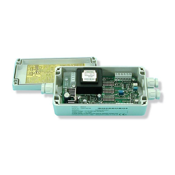
Figure 1.1. Offered in two versions, the COND SGA-A for 110/230V AC or 18-24V DC operation and the COND SGA-D which is DC powered only. Transducer SENSITIVITY of between 0.1 mV/V and 30 mV/V are possible. This is achieved by a combination of gain (span) DIP switches and associated fine adjustment by a potentiometer. -
Page 3: Dimensions
NOTE: Connect the appropriate power to the COND SGA. For AC powering observe the correct transformer jumper connections as shown in Figure 2.2 above. (This diagram is also provided inside the lid). COND SGA-A & SGA-D Manuel_EN Rev3.doc Page 3 on 20... -
Page 4: Input (Sensor) Connections
Do not run signal cable parallel to power cables. Cross such cables at right angles. The ground connection conductor should have sufficient cross-sectional area to ensure a low impedance path to attenuate RF interference. COND SGA-A & SGA-D Manuel_EN Rev3.doc Page 4 on 20 Rev: 03/08/2006... -
Page 5: Output Connections
Select this option by fitting the two jumpers, JP1 and JP2 to the ‘inside’ positions (See Figure 3.2) See Chapter 3 for Switch settings and details of SINK & SOURCE jumpers. COND SGA-A & SGA-D Manuel_EN Rev3.doc Page 5 on 20... -
Page 6: Switch Settings
0↓ 1↑ =Filter in 1↑ Filter out 1↑ =10V Exc 0↓ =5V Exc 4-20mA 1↑ 1↑ 1↑ =Filter in 1↑ Filter out 1↑ =10V Exc 0↓ =5V Exc COND SGA-A & SGA-D Manuel_EN Rev3.doc Page 6 on 20 Rev: 03/08/2006... -
Page 7: Example :- 0-10 Volt Output With No Filter Required
Important: Low pass filtering is switched into operation by setting SW4/6 ‘ON’↑ and SW4/7 ‘OFF’↓. Reverse these settings to bypass the filter. It should be noted that either one of these switches MUST be on but not BOTH COND SGA-A & SGA-D Manuel_EN Rev3.doc Page 7 on 20 Rev: 03/08/2006... -
Page 8: Example : The Switch Settings For A Cut-Off Frequency Of 50 Hz Setting Is Illustrated Below
Ranges 1 to 60 - from 0.06 mV/V to 30.30 mV/V ↑ = ON (1) ↓= OFF (0). SW1/8 switches on the shunt cal function – see Table 3.8 COND SGA-A & SGA-D Manuel_EN Rev3.doc Page 8 on 20 Rev: 03/08/2006... -
Page 9: Sw1
3.4.1. SW1 Table 3.6. COND SGA-A & SGA-D Manuel_EN Rev3.doc Page 9 on 20 Rev: 03/08/2006... -
Page 10: Example : A Strain Gauge Has A Sensitivity Of 2.809 Mv /V
These settings allow the user to calibrate a zero offset. The range allows for up to 79% of the span. Potentiometer P2 provides fine adjustment. + ve Offset - ve Offset Table 3.9. COND SGA-A & SGA-D Manuel_EN Rev3.doc Page 10 on 20 Rev: 03/08/2006... -
Page 11: Example :An Installation Has A Tare Of 15 Kg With A 200Kg Strain Gauge Which Gives An Output Of 6.37Mv/V At 10V Excitation
1/ A 2.5mV/V loadcell provides 10V for an l00Ib load. However it is never loaded above 50lb The sensitivity setting can be set to 1.25 mV/V. Table 3.6 /20 (1.20mV/V SW1 = [1101][000] COND SGA-A & SGA-D Manuel_EN Rev3.doc Page 11 on 20 Rev: 03/08/2006... -
Page 12: Calibration Connections Using Mv Source
Table 3.9. N.B.: It may be necessary to repeat these steps until the required output is achieved. 4.4. Calibration Connections using mV Source Figure 4.1. COND SGA-A & SGA-D Manuel_EN Rev3.doc Page 12 on 20 Rev: 03/08/2006... -
Page 13: Troubleshooting
Check the sensor is connected (typically reading 350 Ohm across output + & - of J2) with the power off. c) Check the Excitation voltage (J2) is at 10V DC COND SGA-A & SGA-D Manuel_EN Rev3.doc Page 13 on 20... -
Page 14: High Output
If the potentiometer does not alter the output the unit must be repaired – remove from service. It is always wise to check a known good COND COND SGA against the problem installation before rejecting the suspect COND COND SGA. COND SGA-A & SGA-D Manuel_EN Rev3.doc Page 14 on 20 Rev: 03/08/2006... -
Page 15: Product Care
A worn out component, excessive use in harsh environments, an overly zealous operator; regrettably some circumstances necessitate repair. At SENSY s.a., we can't guarantee that a product will never require repairing. We can, however, promise a repair service of exceptional quality, one which is governed by a rigorous procedure. - Page 16 The Voltage or Current outputs are calibrated to be directly proportional to the input from the sensor. The output is, within the sensor limits, taken as linear and no linearity compensation is required within the COND SGA. COND SGA-A & SGA-D Manuel_EN Rev3.doc Page 16 on 20 Rev: 03/08/2006...
- Page 17 For example, an COND SGA which measures a load of a 100kg span from 400kg to 500kg is said to have 400kG zero suppression. Alternating Current Direct Current Hertz (Frequency) COND SGA-A & SGA-D Manuel_EN Rev3.doc Page 17 on 20 Rev: 03/08/2006...
-
Page 18: Specifications For Cond Sga/A & Cond Sga/D Load Cell Amplifiers
ºC Storage temperature range ºC Humidity Note 1: 18V max at full load Note 2: Switch SW4/8 on for 10V excitation, + off for 5V excitation (Table 3.2) COND SGA-A & SGA-D Manuel_EN Rev3.doc Page 18 on 20 Rev: 03/08/2006... -
Page 19: Output Options
All COND SGA products from SENSY s.a. are warranted against defective material and workmanship for a period of (3) three years from the date of dispatch. If the SENSY s.a. product you purchase appears to have a defect in material or workmanship or fails during normal use within the period, please contact your Distributor, who will assist you in resolving the problem. -
Page 20: Connection Details
8.8. Connection Details Figure 8.1. COND SGA-A & SGA-D Manuel_EN Rev3.doc Page 20 on 20 Rev: 03/08/2006...
Need help?
Do you have a question about the COND SGA-A and is the answer not in the manual?
Questions and answers