Table of Contents
Advertisement
Quick Links
COND-SGA-A & COND-SGA-D
1. INTRODUCTION .................................................................................................................................................................................2
1.1. The Strain Gauge Amplifier COND-SGA .....................................................................................................................................2
2. INSTALLATION ...................................................................................................................................................................................3
2.1. Pre-installation .............................................................................................................................................................................3
2.2. Wiring ..........................................................................................................................................................................................3
2.2.1. Power connection ................................................................................................................................................................3
2.2.2. Input connection ..................................................................................................................................................................4
2.2.3. Output connections .............................................................................................................................................................4
3. SWITCH SETTINGS............................................................................................................................................................................5
3.1. Switch positions ...........................................................................................................................................................................5
3.2. Analogue output and excitation voltage - SW4 ...........................................................................................................................5
3.3. Output filter settings - SW3 .........................................................................................................................................................7
3.3.1. Output current mode and input filter - JP1, JP2 & JP3 .......................................................................................................7
3.4. Span (gain) setting switch - SW1 ................................................................................................................................................8
3.4.1. Shunt calibration switch - SW1/8 ........................................................................................................................................9
3.5. Zero (offset) setting switch - SW2 ...............................................................................................................................................9
4. CALIBRATION .....................................................................................................................................................................................9
4.1. Output ........................................................................................................................................................................................10
4.2. Zero offset .................................................................................................................................................................................10
4.3. Sensitivity ..................................................................................................................................................................................10
4.3.1. Using a millivolt source .....................................................................................................................................................10
5. TROUBLESHOOTING.......................................................................................................................................................................12
6. PRODUCT CARE ..............................................................................................................................................................................13
7. SPECIFICATIONS .............................................................................................................................................................................13
7.1.1. Output options ...................................................................................................................................................................14
7.1.2. Connections ......................................................................................................................................................................14
7.1.3. Enclosure ..........................................................................................................................................................................14
7.1.4. Controls .............................................................................................................................................................................14
7.2. CE Approvals ............................................................................................................................................................................14
7.3. SGA/A & SGA/D Connection details .........................................................................................................................................15
MA-COND SGA-A & SGA-D_EN.docx
STRAIN GAUGE TRANSDUCER AMPLIFIER
Page 1 on 17
Rev: 09/04/2019
Advertisement
Table of Contents

Subscribe to Our Youtube Channel
Related Manuals for SENSY COND-SGA-A

Summary of Contents for SENSY COND-SGA-A
-
Page 1: Table Of Contents
COND-SGA-A & COND-SGA-D STRAIN GAUGE TRANSDUCER AMPLIFIER 1. INTRODUCTION ....................................2 1.1. The Strain Gauge Amplifier COND-SGA .............................2 2. INSTALLATION ....................................3 2.1. Pre-installation .....................................3 2.2. Wiring ......................................3 2.2.1. Power connection ................................3 2.2.2. Input connection ..................................4 2.2.3. Output connections ................................4 3. SWITCH SETTINGS....................................5 3.1. -
Page 2: Introduction
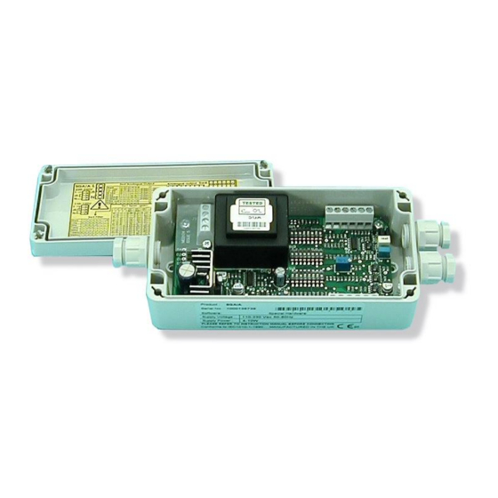
The COND-SGA provides a wide range of signal conditioning for Strain Gauges, Load Cells, Pressure and Torque transducers. Offered in two versions, the COND-SGA-A for 110/230 V AC or 18-24 V DC operation and the COND-SGA-D which is DC powered only. -
Page 3: Installation
5 W (approx. 150 mA fully loaded) NOTE: The COND-SGA-A can be powered from AC or DC sources whichever is available. It is also possible to connect BOTH AC and DC simultaneously for security of power supply. MA-COND SGA-A & SGA-D_EN.docx... -
Page 4: Input Connection
The power supply should be capable of supplying at least 1 A for 12 V installations and 0.5 V for 24 V. Connections to the COND-SGA-A & COND-SGA-D input/output signal and the power supply are made via 2.5 mm² field terminal connectors. -
Page 5: Switch Settings
In ‘Sink’ mode the positive end of the load is connected to the internal +15 V supply on the COND-SGA and the negative end is connected to the COND-SGA output. The current through the load is ‘sunk’ by the COND-SGA towards ground (0 V). In this mode neither connection to the output load is electrically common to the load cell. - Page 6 INPUT OUTPUT OPTION RANGE 4-20 mA 0 – 20 mA 4-20 mA 0 – 20 mA 0 - 10 V 0 - 5 V ±10 V ±5 V + Full Scale 20 mA 20 mA 20 mA 20 mA 10 V 10 V ↑...
-
Page 7: Output Filter Settings - Sw3
0-10 V 0↓ 1↑ 1↑ 0↓ 1↑ Example: - 0-10 Volt output with no filter required 3.3. Output filter settings - SW3 The COND-SGA incorporates a second order (-12 dB/oct) low pass filter which can be switched in to improve the performance and output signal quality in electrically noisy environments. -
Page 8: Span (Gain) Setting Switch - Sw1
3.4. Span (gain) setting switch - SW1 Ranges 1 to 60: from 0.06 mV/V to 30.30 mV/V ↑ = ON (1) ↓ = OFF (0) SW1/8 switches on the shunt cal. function 0.06 mV/V 0.11 mV/V 0.17 mV/V 0.23 mV/V 1 2 3 4 5 6 7 8 1 2 3 4 5 6 7 8 1 2 3 4 5 6 7 8... -
Page 9: Shunt Calibration Switch - Sw1/8
78%. Fine adjustment is provided by potentiometer P2 (±1.25%, and ±79% for both). CALIBRATION The COND-SGA-A & COND-SGA-D provides the excitation supply and signal conditioning to cater for a wide range of strain gauges, load cells, pressure transducers or torque transducers. -
Page 10: Output
1.20 mV/V SW1 = [0010] [000] The COND-SGA-A & COND-SGA-D can be calibrated with the transducer connected, provided that two calibration points can be implemented, e.g. by applying known weights or forces. If this is not possible, a stable mV source or load cell simulator can be used provided that the precise sensitivity (mV/V) and full range output (kg) of the transducer is known. - Page 11 The ‘Ref (5 V/2.5 V)’ should be connected to ‘Strain Input-’ and the mV source applied between ‘Strain Input+’ & ‘Strain Input-’. Set the correct switch settings on SW1 as described above using the transducer's calibration sheet supplied by the manufacturer.
-
Page 12: Troubleshooting
TROUBLESHOOTING No output Check power supply is present (LED is on). Check the output connections are correct. Check terminations (ensure insulation is not trapped in terminal, cable break etc.) Check the sensor is connected (typically reading 350 Ω across Strain Excite + and – and also Strain Input + and –... -
Page 13: Product Care
• A contact phone number from the supplier for assistance SPECIFICATIONS PARAMETER TYPICAL UNITS Power supply COND-SGA-A 110/230 (50 – 60 Hz) V AC COND-SGA-D VDC (See note 1) Current dc (depends on loading) Rejection gain (0 - 100%) 0.01 Rejection offset (0 - 100%) 0.01... -
Page 14: Output Options
Pollution Degree 2 Permanently Connected Insulation Category lll In the interests of continued product development, SENSY S.A. reserves the right to alter product specifications without prior notice. For more Manuals, Quickstarts, Datasheets, support, and many others, visit us on www.sensy.com/support MA-COND SGA-A &... -
Page 15: Sga/A & Sga/D Connection Details
7.3. SGA/A & SGA/D Connection details MA-COND SGA-A & SGA-D_EN.docx Page 15 on 17 Rev: 09/04/2019... - Page 16 Dimensions in mm Terminals J1 J1 J2 J2 J3 J3...
- Page 17 Dimensions in mm Terminals J1 J1 J2 J2...
Need help?
Do you have a question about the COND-SGA-A and is the answer not in the manual?
Questions and answers