
Subscribe to Our Youtube Channel
Related Manuals for Tecfluid CP CH420 Series


Summary of Contents for Tecfluid CP CH420 Series
- Page 1 Instructions manual Series CP CP … CH420 converters The art of measuring R-MI-CH420 Rev.: 1 english version...
- Page 2 PREFACE Thank you for choosing a product from Tecfluid S.A. This instruction manual allows installation, configuration, programming and maintenance. It is recommended to read it before using the equipment. WARNINGS • This document shall not be copied or disclosed in whole or in any part by any means, without the written permission of Tecfluid S.A.
-
Page 3: Table Of Contents
TABLE OF CONTENTS SERIES CP INTRODUCTION ................MODELS ..................ELECTRICAL CONNECTION ............Power supply and analog output ......... Pulse input ................. OPERATION ................. Programming ..............4.1.1 k factor (pulses per liter) ......... 4.1.2 Measuring units ............. 4.1.3 Current loop ............Serial number visualization .......... -
Page 4: Introduction
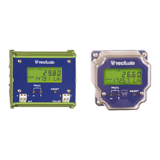
INTRODUCTION The electronic transmitters CP420L and CH420L are designed to work with flowmeters series COVOL and turbines series TM. The instruments are supplied already configured for the type of input. The circuit is based on a microprocessor that, in function of the k factor (pulses per litre) programmed, calculates the flow rate and totalizes the volume that flows through the meter and shows these values on a local indicator. -
Page 5: Pulse Input
Pulse input For the CP … CH420L, sensor connections are the following Terminal n. COVOL Common Ground Live Live — Live For the CP … CH420R, the connection is made directly from the instrument to the terminals 1 and 2, regardless of the polarity. -
Page 6: Operation
OPERATION In order for the instrument indicates an actual flow rate and volume, the k factor specified on the meter must be programmed. To do this, in a CP … CH420L, the plastic cover must be removed by unscrewing the four screws on the corners. After that, the push buttons will be accessible. -
Page 7: Measuring Units
4.1.2 Measuring units In this screen the measuring units can be programmed. To change the flow rate units, the push button marked with the arrow pointing upwards, must be pushed. To change the totalized volume units, the push button marked with the arrow pointing left must be pushed. -
Page 8: Serial Number Visualization
After that, the flow rate equivalent to 20 mA (upper range) can be programmed. In a CH420L, if during the programming sequence it receives a HART command that must be attended, the local programming will not be valid and all the data previously programmed will be lost. -
Page 9: Example Of Useful Calculations
EXAMPLE OF USEFUL CALCULATIONS The calibration of the flowmeters is made with water at 20ºC. If other characteristics from the above specified are used or for reasons of turbulences in the flow, measurement errors can be induced. To correct these types of errors, the k (pulses per litre factor) programmed in the instrument can be modified. -
Page 10: Keyboard Lock And "Write Protect
Numbr of Common Practice Commands Number of Device Specific Commands Bits of Additional Device Status Alternative operating modes? Burst mode? Write Protection? Analog loop electrical characteristics for communications : Reception Impedance: > 8,5 MΩ < 200 pF KEYBOARD LOCK AND “WRITE PROTECT” The transmitter has a jumper situated behind the display on the left hand side which can be used to avoid changes in the configuration. -
Page 11: Input Characteristics
Input characteristics NOTE: The input terminals are not isolated from the 4-20 mA loop. Under no circumstances can an electrical connection be made between the 4-20 mA loop and the inputs. In the event of supplying various transmitters with the same power supply one must make sure that the inputs isolated between each other (except the shields of the turbine pick-ups which can be connected together). -
Page 12: Safety Instructions
SAFETY INSTRUCTIONS The converters series CP are in conformity with all essential requirements of all EC directives applicable to them: 2014/30/EU Electromagnetic compatibility directive (EMC) 2012/19/EU Waste electric and electronic equipment directive (WEEE). 2011/65/EU Directive relating restriction of the use of certain hazardous substances in electrical and electronic equipment (ROHS). -
Page 13: Connecting Conductive Parts To Earth
11.1.2 Connecting conductive parts to earth When the instrument is not grounded securely through the connection process, it should be grounded through the housing screw, as shown in the figure. Earthing screw 11.1.3 Maintenance NOTE: Before any maintenance that involves opening the flameproof enclosure, make sure there is no voltage in any of internal components. -
Page 14: Dimensions
DIMENSIONS All dimensions in mm... - Page 15 All dimensions in mm...
- Page 16 WARRANTY Tecfluid S.A. guarantee all the products for a period of 24 months from their sale, against all faulty materials, manufacturing or performance. This warranty does not cover failures which might be imputed to misuse, use in an application different to that specified in the order, the result of service or modification carried out by personnel not authorized by Tecfluid S.A., wrong handling or accident.
Need help?
Do you have a question about the CP CH420 Series and is the answer not in the manual?
Questions and answers