Table of Contents
Advertisement
Quick Links
Advertisement
Table of Contents

Subscribe to Our Youtube Channel
Related Manuals for Fluigent ESS

Summary of Contents for Fluigent ESS
- Page 1 USER’S MANUAL EASY SWITCH SOLUTIONS MICROFLUIDIC VALVES...
- Page 2 Place the product in an stable location with a level surface and good support. Do not use other power supply than the one provided with the ESS The power supply provided with the ESS has been carefully selected...
-
Page 3: Table Of Contents
SUMMARY INTRODUCTION QUICK START GUIDE 2-SWITCH VALVE Fluidic principles Product overview Fluidic connections Positioning M-SWITCH VALVE Fluidic principles Product overview Fluidic connections Positioning L-SWITCH VALVE Fluidic principles Product overview Fluidic connections Positioning SWITCHBOARD Product overview Connection FLUIDIC CIRCUIT EXAMPLES FREQUENTLY ASKED QUESTIONS TECHNICAL SPECIFICATIONS SERVICING &... -
Page 4: Introduction
L-SWITCH and up to 8 2-SWITCH . The device allows for communication of the SWITCHes to a PC with Fluigent software : Control Microfluidic Automation Tool (MAT) for live control or to automate protocols. It also ensures power supply to the connected... - Page 5 Flow-Rate Platform). (LineUp It is possible to use the ESS™ platform with other flow control systems provided that the pressure applied to the ESS™ devices does not exceed the maximum pressure rating of the valves. Note: To ensure product longevity, the M-SWITCH...
- Page 6 QUICK START GUIDE Here is a quick set-up and quick start guide to summarize of the main steps to get the ESS™ platform up and running. Fluidic connections on the 2-SWITCH™ , M-SWITCH™ and L-SWITCH™ that user wants to use: See page 13 for the 2-SWITCH™...
-
Page 7: Quick Start Guide
USB cable from the SWITCHBOARD to the computer where MAT or ESS™ Control is installed (see page 38) The ESS is now ready to operate either by automating a protocol using the MAT or in live control using the ESS Control software. -
Page 8: 2-Switch Tm Valve
2-SWITCH VALVE The 2-SWITCH™ is a 3-port / 2-position valve. Each of the three ports can be connected with f ittings and tubing to microfluidic set-up or other device. The fluids can be directed bidirectionally into the device with a maximum pressure of 2.5 bar (36 psi). Fluidic principles Fluidic 2-way switch The dark blue “C”... - Page 9 2-SWITCH Fluidic ON/OFF switch 2-SWITCH™ is to plug one of the Another possibility for using the two ports (#1 or #2). This way, one of the positions of the 2-SWITCH™) becomes a closed position, and the 2-SWITCH™ acts as an “ON/OFF” switch.
-
Page 10: Product Overview
2-SWITCH Product overview Product description The front of the 2-SWITCH™. The 3 fluidic ports are located at the front face of the device. The common port is the central one. When looking at the front of the 2-SWITCH™, one can see the LED indicators, 2 points to indicate the port number 2 and a single point to indicate the port number 1. - Page 11 SWITCHBOARD. Plug the cable into a dedicated port on the SWITCHBOARD (blue cable should be plugged in blue port). FLUIGENT recommends to only use the cables provided with the ESS™. 2-SWITCH™ The bottom and the top faces of the...
-
Page 12: Fluidic Connections
NB: There is a wide variety of materials and internal diameters available with 1/16’’ tubing from fittings suppliers to suit ones application. These fittings have been specifically selected by FLUIGENT to ensure good 2-SWITCH™ operation. FLUIGENT advises you to use only these fittings on the 2-SWITCH™. Please note that only tubing of 1/16’’... - Page 13 2-SWITCH How to connect fluidic tubing Cut the 1/16’’ OD tubing to the desired length, leaving a square-cut face. Slide the ¼ -28 fitting over the tubing, with the thread facing outwards. Slip the ferrule over the tubing, with the tapered portion of the ferrule facing the fitting.
-
Page 14: Positioning
2-SWITCH Positioning There are several ways to position the 2-SWITCH™. The 2-SWITCH™ can be used in any spatial configuration. Vertically Horizontally On side Stacked... -
Page 15: M-Switch Tm Valve
M-SWITCH VALVE The M-SWITCH™ is an 11-port / 10-position valve. This means that eleven (11) ports can be connected with tubing, such that it is possible to choose between ten (10) individual positions linking one of the ten (10) external ports to the central port of the valve. Fluidic principles Fluidic rotary switch M-SWITCH™... - Page 16 M-SWITCH Bidirectional M-SWITCH™ is a bidirectional valve. The fluid can flow inside the M-SWITCH™ in both directions. This feature plus the rotary capabilities allow different ways of use. Distributor mode: fluid flows from the central port to one external port (according to the selected position).
-
Page 17: Product Overview
M-SWITCH Product overview Description Photo of the M-SWITCH™. The connection ports are located on the head of the valve. 10 external ports are placed radially, and the common central port is located vertically at the center of the head. To connect tubing, standard flangeless connectors are required. - Page 18 An RJ45 cable connects the M-SWITCH™ to the SWITCHBOARD. Plug the cable into dedicated port on the SWITCHBOARD (white cable should be plugged in white port). Only use the cables provided with the ESS™ for ESS™ operation. Control To the PC Power supply...
-
Page 19: Fluidic Connections
• Flat-bottom type (FB). • Tubing compatibility: 1/16’’ external diameter (1/16’’ OD). Fluigent provides the following contents: 20 * Flat bottom ferrules 1/16'' 11 * Plug Delrin® - ¼-28 Flat Bottom 11 * ¼-28 connectors for 1/16’’ OD tubing 2.5 m of FEP tubing: 1/16’’OD (500µm ID) - Page 20 M-SWITCH How to connect fluidic tubing Cut the 1/16’’ OD tubing to the desired length, leaving a square-cut face. Slide the ¼ -28 fitting over the tubing, with the thread facing outwards. Slip the ferrule over the tubing, with the tapered portion of the ferrule facing the fitting.
-
Page 21: Positioning
M-SWITCH Positioning The M-SWITCH™is lested in order to have the best stability when placed on a surface. The M-SWITCH™ can be used in standing position or horizontally as long as it is stable. Horizontally Standing... -
Page 22: L-Switch Tm Valve
VALVE The L-SWITCH™ is a 6-port / 2-position, bidirectional valve for injection or switching different fluids. The switch position and timing may also be automated using Fluigent Microfluidics Automation Tool software (MAT). Fluidic principles Fluidic switching mode L-SWITCH™ The fluid paths of the are shown below. - Page 23 L-SWITCH Fluidic injection mode L-SWITCH™ with a sample loop. In this config- It is possible to use the uration, position 1 of the L-SWITCH™ becomes a load position, and the position 2 is an inject position. In this mode, the L-SWITCH™ enables to inject a precise volume of fluid, corresponding to the sample loop size Load sample Sample loop...
-
Page 24: Product Overview
L-SWITCH Product overview Description Photo of the L-SWITCH™. The 6 connection ports are located on the head of the valve. To connect fluidic tubing, one PEEK fingertight must use connectors 10-32. The head of the L-SWITCH™ is made up of the Ram which holds the fluidics ports and a Spanner. - Page 25 A. The orange LED lights up when the valve is powered. B. The green LED lights up if a "connection check" has been requested by the SWITCHBOARD. Only use the cables provided with the ESS™ for operation. Control To the PC Power supply...
-
Page 26: Fluidic Connections
Thread-size: 10-32 • Tubing compatibility: 1/16’’ external diameter (1/16’’ OD). To get started, Fluigent provides the following contents: 7 * 10-32 Coned fingertight fittings 1/16'' OD 2 * 10-32 Delrin® Coned blue plug 1 * 10-32 to Female Luer connector 1 m of FEP tubing: 1/16’’OD... - Page 27 L-SWITCH How to connect fluidic tubing Cut the 1/16’’ OD tubing to the desired length, leaving a square-cut face. Insert the tubing into a nut until it passes 1.5 - 3mm Insert into a port of L-SWITCH™, twist until it is tightened. You can pull gently the tubing to verify that it is securely connected to the port.
- Page 28 (nuts and ferrules are provided with the sample loop). There is a large selection of sample loops of different volumes. Please contact us at contact@fluigent.com for more information. Pass one end of the sample loop through a nut...
- Page 29 L-SWITCH Using the sample loop A sample loop is used to inject a precise volume of liquid. In this example, the fluid circuit enters from the port 2 and exits from the port 3. In position 1, the sample can be loaded into the loop.
- Page 30 L-SWITCH Connecting a syringe injector to the valve Syringes are often used to load a sample loop (See the previous example p.32) To do so, one needs to use the adaptor provided to connect a syringe needle to the L-SWITCH™ Unscrew the adaptor set to separate the nut from the adaptor Insert 1/16’’...
-
Page 31: Positioning
L-SWITCH Positioning L-SWITCH™ There are several possibilities to set the The L-SWITCH™ can be used in any spatial conf iguration. Horizontally Vertically Other possibilities T h e ¼ - 2 0 ’ ’ i n s e r t o n t h e b o t t o m f a c e o f t h e L-SWITCH™... -
Page 32: Switchboard
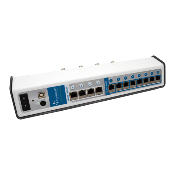
MAT software (and the ESS The ESS Control software if used with a SWITCHBOARD) To download them, use the FSI Fluigent Software Installer (for ESS Control only) or the provided USB stick. Product overview Photo of the SWITCHBOARD. - Page 33 The green indicator lights up if a “Check connection” identification has been requested for the device connected to the port from the corresponding Check connection push button on the SWITCHBOARD or from the ESS™ Control software (cf. ESS™ Control User Manual).
-
Page 34: Connection
“power”. The flat side of the power supply plug must face upwards to connect the socket to the SWITCHBOARD. One can now actuate the ON/OFF power switch to turn the SWITCHBOARD ON and OFF. Only use the power supply provided with the ESS™. - Page 35 SWITCHBOARD Connection to PC Connect the type B plug of the USB cable provided with the ESS™ into the type B USB port on the front of SWITCHBOARD labeled “USB”. Connect the other end of the USB cable (type A standard plug) to ESS™...
- Page 36 ‘White cable’ SWITCHBOARD section (A to D) and connect the 2-SWITCH™ RJ45 to ports located in the ‘Blue cable’ SWITCHBOARD section (1 to 8) on the SWITCHBOARD. If one connects a valve to a wrong port, it can damage the ESS™ devices.
-
Page 37: Fluidic Circuit Examples
EXAMPLES FLUIDIC CIRCUIT EXAMPLES Sequential injection In this application example, up to 10 liquids (4 on the schematic) are M-SWITCH selected sequentially to be delivered to the chip by the The samples at the outlet of the chip may also be sorted by using a 2-SWITCH either into a collection tube or to waste. - Page 38 INTRODUCTION Sample generation and collection In this application example, different concentrations of the molecule of interest are combined into water in oil droplets. These droplets are then sorted at the outlet of the chip using the M-SWITCH Concentration Molecule of interest M-SWITCH LineUp Flow EZ...
- Page 39 INTRODUCTION Sample preparation Several samples are injected simultaneously or separately within a Y-shaped chip by changing the position of the three 2-SWITCH placed at the chip inlets. The mix by diffusion and the samples at 2-SWITCH the outlet are then sorted by a fourth Each step can be automated either by using Microfluidic Automation Tool (MAT)
- Page 40 INTRODUCTION Fluid recirculation L-SWITCH™ can be used when a small volume of buffer can be recirculated within a closed loop into the chip for several hours or days. Combined with the LineUp pressure regulation it can achieve highly stable flow with a positive impact on the shear stress. The Microfluidic Automation Tool (MAT) allows one to switch the valve position and the pressurized reservoir so that the flow is maintained...
- Page 41 INTRODUCTION Accurate volume injection Sample from the reservoir is loaded into a "sample loop" between two outlets of the L-SWITCH while carrier buffer is directly injected L-SWITCH position is switched the sample into the chip. When the loop volume is injected into the chip along with carrier buffer. The sample is then sorted by the 2-SWITCH at the outlet of the chip.
-
Page 42: Frequently Asked Questions
FREQUENTLY ASKED QUESTIONS With a fluidic “ON/OFF” switch configuration, should I fill with liquid the plugged path inside the 2-SWITCH™ before screwing the plug? If you are planning to use a 2-SWITCH™ as a fluidic ON/OFF switch, you will need to plug either port #1 or port #2 on the 2-SWITCH™. As an example if you plug port #2, when in Position 2 the common port will be connected to the plug inside the 2-SWITCH™. - Page 43 SWITCHBOARD (one for each RJ45 port) This will light up the green RJ45 indicators on the associated SWITCHBOARD RJ45 port and on the RJ45 port of the device connected to it. Other methods are applicable if using Fluigent software.
-
Page 44: Technical Specifications
TECHNICAL SPECIFICATIONS 2-SWITCH Pressure rating Up to 2,5 bar (36 psi) Internal volume 28 µL Wetted materials PEEK, PPS, FFKM, Mineral oil is not FKM, EPDM compatible with EPDM Response time 3 ms Dimensions 80 * 65 * 20 mm Weight 89 g M-SWITCH... - Page 45 SPECIFICATIONS L-SWITCH Pressure rating Up to 7 bar (100 psi) Internal volume 660 nL Wetted materials PEEK Response time 100 ms Dimensions 70 * 90 * 150 mm Weight 475 g SWITCHBOARD Input 6.67 A 160 W max Dimensions 343 * 99,4 * 58,4 mm Weight 1228 g...
-
Page 46: Servicing & Warranty
SERVICING & WARRANTY Schedule Component Servicing interval All system Regular inspection for external damage / leaks SWITCHBOARD Regular inspection for external damage / leaks 2-SWITCH Regular inspection for external damage / leaks M-SWITCH Regular inspection for external damage / leaks L-SWITCH Regular inspection for external damage / leaks Cleaning... -
Page 47: Warranty Terms
What This Warranty Covers This warranty is granted by Fluigent and applies in all countries. Your Fluigent product is guaranteed for one year from the date of delivery at your lab- oratory against defects in materials and workmanship. If found to be defective within the warranty period, it will be repaired or replaced free of charge. - Page 48 VERSION FEB. 2021...
Need help?
Do you have a question about the ESS and is the answer not in the manual?
Questions and answers