Table of Contents
Advertisement
Quick Links
Advertisement
Table of Contents

Related Manuals for Fluigent ESS

Summary of Contents for Fluigent ESS
- Page 1 USER’S MANUAL EASY SWITCH SOLUTIONS MICROFLUIDIC VALVES...
- Page 2 Do not place the product in an unstable location with a level surface and a strong and stable support Do not use other power supply than the one provided with the ESS The power supply provided with the ESS has been carefully selected...
-
Page 3: Table Of Contents
Fluidic principle Product overview Fluidic connections Positionning L-SWITCH VALVE Fluidic principle Product overview Fluidic connection Positionning SWITCHBOARD Product overview Connection HOW TO USE ESS WITH GAS HOW TO START WORKING WITH THE ESS FREQUENTLY ASKED QUESTIONS TECHNICAL SPECIFICATIONS SERVICING & WARRANTY... -
Page 4: Introduction
INTRODUCTION The Easy Switch Solution platform (ESS ) provides solutions for path selection in microfluidics. The Easy Switch Solutions platform enables one to implement 3 different kind of valves in a microfluidic circuit. 2-SWITCH is a 3-port/2-position solenoid valve: 2 ports can alternatively be connected to a third one. - Page 5 Flow-Rate Platform). (LineUp It is however possible to use the ESS™ platform with other flow control systems provided that the pressure applied to the ESS™ devices does not exceed 7 bar (~ 100 psi) Note: To ensure product longevity, the M-SWITCH...
-
Page 6: Fluidic Circuits Examples
INTRODUCTION Fluidic circuits examples Sequential injection In this application example, up to 10 liquids (4 on the schematic) are selected sequentially inside the 1-channel chip by the M-SWITCH The samples at the outlet of the chip are sorted by a 2-SWITCH either into a collector tube or into a waste. - Page 7 INTRODUCTION Sample preparation and collection In this application example, different concentration of the molecule of interest are injected into the chip thus generating droplets with different concentrations. These droplets are then sorted at the outlet of the chip by the M-SWITCH depending on their concentrations.
- Page 8 INTRODUCTION Sample preparation Several samples are injected simultaneously or separatly within a Y-shaped chip by changing the position of the three 2-SWITCH placed at the chip inlets. The injected solutions into the chip are mixed by diffusion and the samples at the outlet are then sorted by the fourth 2-SWITCH Each step can be automated either by using...
- Page 9 INTRODUCTION Fluid recirculation L-SWITCH™ can be used as a useful cell culture tool: a small volume of buffer can be recirculated within a closed loop into the chip for several hours or days. Combined with the LineUp pressure regulation it can achieve a highly stable flow with a positive impact on the shear stress.
- Page 10 INTRODUCTION Controlled volume injection Sample from the reservoir is loaded into a "sample loop" between two outlets of the L-SWITCH while carrier buffer is directly injected L-SWITCH into the chip. When the position is switched the controlled sample loop volume is injected into the chip along with carrier buffer.
-
Page 11: Fluidic Principle
2-SWITCH VALVE The 2-SWITCH™ is a 3-port / 2-position valve. Each of the three ports can be connected with f ittings and tubings to microfluidic set-up or other device. The fluids can be flown bidirectionally into the device with a maximum pressure of 7 bar (100 psi). Fluidic principles Fluidic 2-way switch See below the fluidic diagram of the 2-SWITCH™. - Page 12 2-SWITCH Fluidic ON/OFF switch 2-SWITCH™ is to plug one of the Another possibility for using the two ports (#1 or #2). This way, one of the positions of the 2-SWITCH™) becomes a closed position, and the 2-SWITCH™ acts as a fluidic “ON/OFF”...
-
Page 13: Product Overview
2-SWITCH Product overview Product description See below a picture of the front of the 2-SWITCH™. The 3 fluidic ports are located at the front face of the device. The common port is the central one. When looking at the front of the 2-SWITCH™, one can see the LED indicators, 2 points to indicate the port number 2 and a single point to indicate the port number 1. - Page 14 SWITCHBOARD. Connect the cable into dedicated port on the SWITCHBOARD (blue cable should be plugged in blue port). Other types of cables can damage the ESS™. Similarly, the cables provided with the ESS™ should not be used other applications.
-
Page 15: Fluidic Connections
2-SWITCH™. Please note that only tubings of 1/16’’ external diameter should be used with the 2-SWITCH™. FLUIGENT does not recommend the use of other tubings sizes with or without tubing sleeves, as it can damage... - Page 16 The conectors and ferrules are specifi- cally designed to work together. FLUIGENT advises you to only use the provided ferrules together with the provided nuts. Insert the assembly into the receiving...
-
Page 17: Positionning
2-SWITCH Positionning There are several ways to position the 2-SWITCH™. Please note that the 2-SWITCH™ device does not have any imposed mounting orientation. The 2-SWITCH™ can be used in any spatial configuration. Vertically Horizontally On side Stacked... -
Page 18: Fluidic Principle
M-SWITCH VALVE The M-SWITCH™ is an 11-port / 10-position valve. This means that eleven (11) ports can be connected with tubings, and that it is possible to choose between ten (10) positions linking one of the ten (10) external ports to the central port of the valve. Fluidic principles Fluidic rotary switch See below the fluidic diagram of an M-SWITCH™. - Page 19 M-SWITCH Bidirectional valve M-SWITCH™ is a bidirectional valve, meaning that the fluid can flow inside the M-SWITCH™ in both directions. This feature plus the rotary capabilities allow different way of use. Distributor mode: fluid flows from the central port to one external port (according to the selected position).
-
Page 20: Product Overview
M-SWITCH Product overview Product description See below a picture of the M-SWITCH™. connection ports located on the head of the valve. 10 external ports are placed as a "sun like" configuration, and the common central port is located verticaly at the center of the head. -
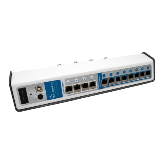
Page 21: Switchboard
SWITCHBOARD. Connect the cable into dedicated port on the SWITCHBOARD (white cable should be plugged in white port). Other types of cables can damage the ESS™. Similarly, the cables provided with the ESS™ should not be used other applications. - Page 22 NB: There is a wide variety of materials and internal diameters available with 1/16’’ tubing from fittings suppliers to suit ones application. These fittings have been specifically selected by FLUIGENT to ensure good M-SWITCH™ operation. FLUIGENT advises you to use only these fittings on the M-SWITCH™. Please note that only tubings of 1/16’’...
- Page 23 The conectors and ferrules are specifi- cally designed to work together. FLUIGENT advises you to only use the provided ferrules together with the provided nuts. Insert the assembly into the receiving...
- Page 24 2-SWITCH Positionning The M-SWITCH™is lested in order to have the best stability when placed on a surface. Please note that the M-SWITCH™ device does not have any imposed mounting orientation. The M-SWITCH™ can be used in standing position or horizontally as long as it is stable. Horizontally Standing...
- Page 25 VERSION SEP. 2020...
Need help?
Do you have a question about the ESS and is the answer not in the manual?
Questions and answers