Table of Contents
Advertisement
Quick Links
EVE MOVE 30kW
Charger User Manual
Ver: V1.8
Released time: 2020-06-
03 BOM:
201040105
EV Expert s.r.o.
VAT ID: CZ05699711
Stupkova 18, 779 00 Olomouc Czech Republic
For more information visit:
All rights reserved. This Manual may be subject to change without notice
.
Tested according to:
www.evexpert.eu
IEC 61851-1
IEC 61851-23
IEC 61851-24
EN 61851-1
EN 61851-23
EN 61851-24
Advertisement
Table of Contents

Related Manuals for EVEXPERT EVE MOVE 30kW


Summary of Contents for EVEXPERT EVE MOVE 30kW
- Page 1 EVE MOVE 30kW Charger User Manual Ver: V1.8 Released time: 2020-06- 03 BOM: 201040105 EV Expert s.r.o. VAT ID: CZ05699711 Stupkova 18, 779 00 Olomouc Czech Republic For more information visit: www.evexpert.eu All rights reserved. This Manual may be subject to change without notice...
- Page 2 Important safety instructions Please read the operating instructions and notes carefully before starting operation,in order to Ø prevent accidents. The "Caution, Attention, Warning and Danger" statements in the products and product manual do not represent all safety matters to be observed and are intended to supplement various operational safety precautions.
- Page 3 A strong electromagnetic field will be produced in the atmosphere under the thunderstorm. Therefore, the equipment should be well grounded to avoid damage to the equipment due to lightning strikes. Static Electricity Static electricity generated by the human body may damage electrostatic sensitive components on the circuit boards, such as the large-scale integrated circuit (IC), etc.
-
Page 4: Table Of Contents
TABLE OF CONTENTS 1 GENERAL PRODUCT DESCRIPTION ......................... 2 2 GENERAL CHARACTERISTIC ............................. 3 2.1 Technical characteristics ................................3 2.2 Standards ....................................4 3 PRODUCT PARTS PRESENTATION ........................... 5 INSTALLATION ................................7 4.1 Safety and compliance ................................7 4.2 Grounding instructions ................................7 4.3 Unpacking and visual inspection .............................7 4.4 Assembly/placing instructions ..............................7 4.4.1 Anchoring to the wall or the concrete PAD .........................7 4.4.2Power cables connections ............................ -
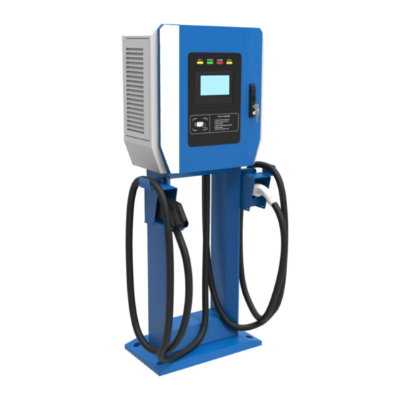
Page 5: General Product Description
1 GENERAL PRODUCT DESCRIPTION The EVE MOVE 30kW is able to fast charge all electric vehicles compliant Ø with CHAdeMO charging system and combined charging system (CCS) standards. Which specially designed for Wall mounting or stand Ø column installation. Integrated design with wall mounting structure,small size and light weight,easy and multi... -
Page 6: General Characteristic
2 GENERAL CHARACTERISTIC Technical characteristics EVE MOVE 30kW technical characteristics are indicated in the Table 1. This unit is intended to have at least one DC output connection (CCS and/or CHAdeMO) and in addition can have one of the two AC output1 connections (AC22). -
Page 7: Standards
AC and DC output connections can charge simultaneous: Ø The total nominal current input needed is 80A. 2.2 Standards The EVE MOVE 30kW complies with the following standards: Table 2 –EVE MOVE 30kW Applicable Standards Technical Data Remarks IEC 61851-1... -
Page 8: Product Parts Presentation
DC connector). Table 3 –EXP30K1-FDW product name and model Name Model Capacity 500V, CCS Combo2+CHAdeMO,30KW EVE MOVE 30kW EVE MOVE 30kW Optional AC22 charging connector/socket EVE MOVE 30kW has 11 possible output combinations as showed below:... - Page 9 Output Configurations: CHAdeMO CCS2 CCS1 CCS1 CCS2 CHAdeMO CCS1+CHAdeMO CCS2+CHAdeMO CCS1+CCS1 CCS2+CCS2 CCS1+GBT CCS2+GBT GBT+CHAdeMO Optional:AC charging connector or socket AC connector AC socket...
-
Page 10: Installation
Check if the exterior packaging has been damaged by mechanical impacts or any accidents Ø during transportation If applicable, check if the exterior panels of the EVE MOVE 30Kw are in perfect condition Ø Check if the interior of the Quick Charger Station is clean Ø... - Page 11 ¬EVE MOVE 30kW Drilling and conduits layout-1¬ Grid input wiring...
- Page 12 ¬EVE MOVE 30kW Drilling and conduits layout-2¬...
-
Page 13: 2Power Cables Connections
4.4.2 Power cables connections End terminals for input wiring: UPPERAC INPUT EXP30K1-FDW 5(five) end terminals up to 3phases+neutral+protective ground. Table3-AC input wiring cables choose The section for AC feed cables Amperage at 380Vac Max. Power of charger 10mm2 ~16mm2 (90℃) 30kW 16mm2 ~25mm2 (90℃) 30kW +22kW... - Page 14 TYPE1: CCS2+CHAdeMO ※ PE: Earth Bus Bar ※ XT1: Power main input-Terminal Block: L1 L2 L3 N ※ Q1: AC Input MCB For Rectifier Module ※ Q2: AC InputRCDForAuxiliary Power TYPE2: CCS2+CHAdeMO+AC Type2 Socket ※ Q3: AC Input MCB For AC22 ※...
-
Page 15: Power Module Installation
4.4.3 Power Module Installation STEP-1 STEP-2 STEP-3 STEP-4... - Page 16 ※ Step-1:remove the nuts in the cabinet (marked with a red circle). ※ Step-2:plug the power module(s) into the module slot(s) inside the cabinet, before plug the power module(s) must be noticed the install position(marked with a red circle). ※ Step-3: Plug the power modules all, and locknut tightly(marked with a red rectangle). ※...
- Page 17 TYPE 3: Attention: all the power modules needto set to 1(0x000001) Note: If the system is just configured to 15kW output power, then one power module will be removed. The empty power module slot must be covered by a blanking plate. Otherwise, the system thermal management will not function correctly.
-
Page 18: Start-Up
5 START-UP Verification and inspection Check if the bolts of the AC and protective ground cables of the EVE MOVE 30kW are Ø correctly tightened to the specified torque Check the resistance between the EVE MOVE 30kW protective ground and the low Ø... - Page 19 CCS2+CHAdeMO+AC Type2 Socket Units: (Q4) Type BRCD For AC22 (Q3) AC Input MCB For AC22 (Q2) AC Input RCD For Auxiliary Power (Q1) AC Input MCB ForRectifier Module Wait for a fess seconds. The display will present a picture as below: Ø...
- Page 20 SAFETY INSTRUCTIONS IN THIS MANUAL HAVE BEEN CAREFULLY READ AND OBSERVED BY TECHNICALLY COMPETENT PERSONNEL. KEEP THIS MANUAL WITH THE EVE MOVE 30kW FOR FUTURE REFERENCE. THIS EVE MOVE 30kW MUST NOT BE STARTED OR PUT INTO USE WITHOUT HAVING BEEN COMMISSIONED BY A FULLY TRAINED AND AUTHORIZED PERSON.
-
Page 21: User Manual
During the charging process, the Human Machine Interface (HMI), will give instructions and will signal different stages. These sequences are shown in this chapter. 6.1 Output connector The EVE MOVE 30kW is prepared to charge electric vehicles according to the mentioned charging systems 6.1.1CCS Connector... - Page 22 6.1.2 CHAdeMO Connector CHAdeMO connector has a lock button. CHAdeMO CHAdeMOConnector Handing 6.1.3 AC Connector or socket AC TYPE-2 Type2 handing AC SOCKET Connector for AC22 handing...
-
Page 23: Operation Instructions
6.2 Operation instructions When a user starts an operation on the EVE MOVE 30kW, the HMI display will show one of the following screens if: All output connections are idle or, the unit allows the charging of DC and ※... -
Page 24: Ethernet And Occp Setting
6.2.1 Options interfaces 3.3 Ethernet and OCCP setting There are 2 standard parameters for back-end setting. Please get them from the back-end supplier. -Charger ID -OCPP Server End Url Figure 12. Example from OCPP-J 1.6 spec (Note: The protocol upper controller supports is OCPP-J 1.6, please refer to the OCPP official documents if you have any question about the above 2 parameters or the protocol itself) Connection Check If the above settings are done properly, you should see the ‘... -
Page 25: Charger Software Update
3.5 Charger software update The charger can update the firmware by OCPP, and also support the local update by Micro SD card to update the upper controller’s firmware and by USB disk to update the pilot controller’s firmware. For upper controller’s update, firstly power on the controller, and then plug the Micro SD card into the controller’s SD inlet, and then go into the setting in“Manual Ctrl”->“Charger System”->“Reboot System”, need to input “... -
Page 27: Appendix 1 Engineering And Technical Parameters
Appendix 1 Engineering and Technical Parameters ※ The DC Charger has left-side and right-side doors. Aminimum 100cm clearance should be provided on both sides to provide space for maintenance. ※ Hot ventilation air exits to the left. A minimum150cm clearance should be provided to prevent hot air from recirculating back to the air intake. -
Page 28: Appendix 2 Schematic Diagram
Appendix 2 Schematic Diagram... -
Page 29: Appendix 3Error Codes And Possible Solutions
Appendix 3Error codes and possible solutions... - Page 30 Table: Charger_Alarms Alarm_ID Alarm_Name Alarm_Level Description Remark System is out of service and charge is not allowed. This System Not usually comes after other Availabe critical alarm(e,g EPO pressed) System is out of service and charge is not allowed. This System Diabled happens after system is set to 'In-operative' by service...
- Page 31 abnormal This is from IMSU-D when PLC ComFail Alarm the PLC communication is lost This is from IMSU-D after Ground Fault detected ground fault This is from IMSU-D after AC Fail Alarm(for detected AC gun input AC only) fails(DI) The communication between IMMU2 and Card Reader is failed.
- Page 32 Stop Reason Code Description Remark Classification Normal Stop Condition satisfied Normal Stop EV Requst Stop EV Reqest Stop Parameter configuration failed Charging Enable timeout Abnormal volt of outside bus Unable lock charging gun Insulation inspection abnomaly Insulation inspection timeout EV Relay pull-In timeout Require Curr Timeout Remain time over stop Ring fail alarm (reserved)
- Page 33 Battery overvoltage Battery undervoltage Battery current deviation error High battery temperature Battery voltage deviation error Charger Connector Lock Fault EV Error Vehicle shift position Error Status Noticed by EV PLC Low Level Comm Fail PLC High Level Comm Fail PLC Authentication Timeout PLC ParamDiscovery Timeout Local Stop Server Stop...
Need help?
Do you have a question about the EVE MOVE 30kW and is the answer not in the manual?
Questions and answers