
Related Manuals for matev TRL-3D 20

Summary of Contents for matev TRL-3D 20
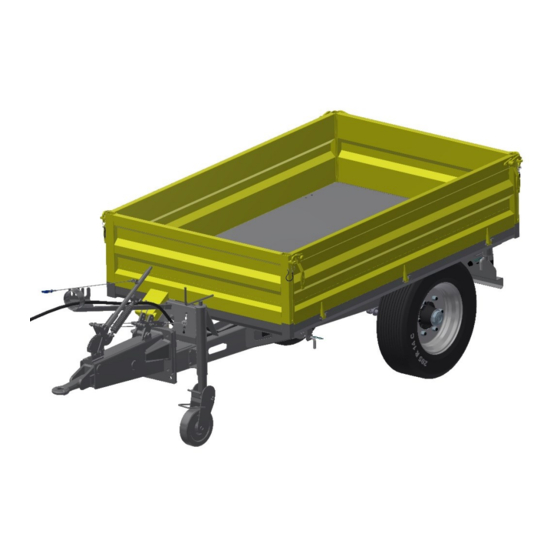
- Page 1 GmbH Nürnberger Str. 50 90579 Langenzenn www.matev.eu Installation Manual Art. no. 131 8849 Chassis TRL-3D 20 Version 2020-04...
-
Page 2: Important Notices
Remove the assembly aids. The assembly steps are explained in the referenced documentation. If this documentation is not available to you, please contact matev GmbH. Assembly steps for which no tools are needed. Use only suitable tools Use suitable, calibrated tools and comply with the specified torque for threaded connections. - Page 3 Assembly 2 Assembly 365 ±15 Nm M20 hex nut Limes-type conical spring washer DIN 74361-C Check tire pressure. Page 3...
- Page 4 Assembly Appendix A Page 4...
- Page 5 Assembly 55 Nm DIN 933 M10x30-8.8 DIN 985 M10-8 DIN 126-11 Page 5...
- Page 6 Assembly 475 Nm DIN 933 M20x60-8.8 DIN 933 M20-8 Wedge-locking wash- Page 6...
- Page 7 Assembly Appendix A Appendix A EN 1665 M8x20-8.8 DIN 985 M10-8 DIN 126-11 Page 7...
- Page 8 Appendix A 1. Appendix A Adjustment of the overrun brake with automatic reverse The brake system consists of a telescoping drawbar and a braked axle, which are con- nected by means of a mechanical gearbox. The brake is activated by the force exerted between the trailer and the towing vehicle when the towing vehicle slows down.
- Page 9 Figure 1: Schematic representation of the brake system Figure 2: Adjusting the brake Page 9...
- Page 10 Appendix A Functional characteristics of the braking system Driving forward without brakes The brake shoes B1 and B2 do not contact the drum T. They are held in position by the spring F1 and the levers A and G. The wheel turns freely.
- Page 11 Free reverse gear. When driving in reverse, the friction resistance between the brake drum and the brake shoe B2 presses the brake shoe B2 against the eccentric A. The contact between the eccen- tric and the brake shoe B2 is main- tained by the spring on the eccen- tric.
Need help?
Do you have a question about the TRL-3D 20 and is the answer not in the manual?
Questions and answers