Table of Contents
Advertisement
Quick Links
Advertisement
Table of Contents

Subscribe to Our Youtube Channel
Related Manuals for AXIOMTEK UST200-83H-FL


Summary of Contents for AXIOMTEK UST200-83H-FL
- Page 1 UST200-83H-FL Robust DIN-rail Fanless Embedded System User’s Manual...
- Page 2 Axiomtek does not make any commitment to update the information in this manual. Axiomtek reserves the right to change or revise this document and/or product at any time without notice. No part of this document may be reproduced, stored in a retrieval system, or transmitted, in any form or by any means, electronic, mechanical, photocopying, recording, or otherwise, without the prior written permission of Axiomtek Co., Ltd.
-
Page 3: Safety Precautions
Safety Precautions Before getting started, please read the following important safety precautions. The UST200-83H-FL does not come equipped with an operating system. An operating system must be loaded first before installing any software into the computer. Be sure to ground yourself to prevent static charge when installing the internal components. -
Page 4: Classification
Classification Degree of production against electric shock: not classified Degree of protection against the ingress of water: IP20 Equipment not suitable for use in the presence of a flammable anesthetic mixture with air or with oxygen or nitrous oxide. Mode of operation: Continuous General Cleaning Tips You may need the following precautions before you begin to clean the computer. -
Page 5: Cleaning Tools
Cleaning Tools Although many companies have created products to help improve the process of cleaning your computer and peripherals users can also use household items to clean their computers and peripherals. Below is a listing of items you may need or want to use while cleaning your computer or computer peripherals. -
Page 6: Scrap Computer Recycling
Trademarks Acknowledgments Axiomtek is a trademark of Axiomtek Co., Ltd. IBM, PC/AT, PS/2, VGA are trademarks of International Business Machines Corporation. ®... -
Page 7: Table Of Contents
Table of Contents Disclaimers ii Safety Precautions ....................iii Classification ......................iv General Cleaning Tips ....................iv Cleaning Tools ......................v Scrap Computer Recycling ..................vi SECTION 1 INTRODUCTION................1 General Description ................1 System Specifications ................2 Dimensions ................... 7 I/O Outlets ..................... - Page 8 This page is intentionally left blank. viii...
-
Page 9: Section 1 Introduction
Pre-installed with Linux and Windows 10, the UST200-83H-FL provides programmers with a friendly environment for developing application software at a lower cost. By supporting mSATA, the UST200-83H-FL also serves as a perfect field control & monitoring system solution for the following markets: ... -
Page 10: System Specifications
UST200-83H-FL User’s manual O.S. Supported ® Windows 10 and Linux Ubuntu 18.04 LTS System Specifications 1.2.1 Onboard Intel ® ATOM™ E3930 (1.3 GHz/2-core) processor. 1.2.2 BIOS AMI(American Megatrends Inc.) UEFI(Unified Extensible Firmware Interface) BIOS. 1.2.3 System Memory ... - Page 11 UST200-83H-FL User’s Manual 1.2.8 2 USB 2.0 ports USB Pin Define: USB 2.0 Signal Signal USB2.0 Port 1 USB2.0 Port 2 1.2.9 COM (COM SKU) 1 port DB9 supports RS-232/422/485, which can be selected by BIOS.
- Page 12 UST200-83H-FL User’s manual 1.2.11 One DB9 female connector supports 8 bits TTL level programmable digital input/output The voltage of TTL is 5V The programming is as follow: I/O sink current is 8~10mA Input/Output is programmable...
- Page 13 UST200-83H-FL User’s Manual 1.2.14 Restore BIOS Optimal Defaults (SW1) Press the tact switch (SW 1) 4 seconds to restore optimal BIOS defaults. 1.2.15 System LED The table below summarizes the functional descriptions of the LED indicators and their corresponding colors.
- Page 14 UST200-83H-FL User’s manual 1.2.21 System I/O Outlets 1 x 9-pin D-Sub male connector, COM1. (COM SKU) 1 x 9-pin D-Sub male connector, CANBus 2.0A/B (CAN SKU) 1 x 15-pin D-Sub female connector for VGA. ...
-
Page 15: Dimensions
UST200-83H-FL User’s Manual Dimensions The following diagrams show you the dimensions and outlines of the UST200-83H-FL. Introduction... -
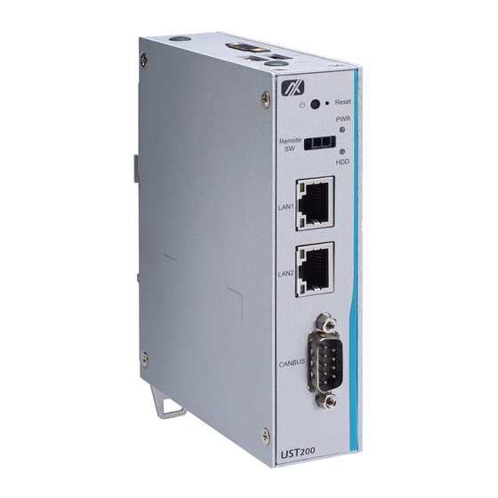
Page 16: I/O Outlets
UST200-83H-FL User’s manual I/O Outlets The following figures show you the I/O outlets on the front view and top view of the UST200- 83H-FL. Introduction... - Page 17 UST200-83H-FL User’s Manual The following figures show you the I/O outlets on the front view and bottom view of the UST200-83H-FL. Introduction...
- Page 18 UST200-83H-FL User’s manual This page is intentionally left blank. Introduction...
-
Page 19: Section 2 Hardware Installation
UST200-83H-FL User’s Manual SECTION 2 HARDWARE INSTALLATION The UST200-83H-FL is convenient for your various hardware configurations, such as memory modules and mSATA drives. Chapter 2 will show you how to install the hardware. Installing the Memory Module Step 1 Turn off the system. - Page 20 UST200-83H-FL User’s manual Step 4 Use two fingers to hold the memory module, and insert the gold contact into the slot and push the module down. Step 5 The memory module is locked by two latches on the sides. We strongly recommend using “LDC737”...
-
Page 21: Installing The Msata
UST200-83H-FL User’s Manual Installing the mSATA Step 1 Turn off the system. Step 2 Loosen all screws of the cover and remove the cover from the system. Insert the mSATA into the slot with the marking “mSATA / USB / PCIe ”. -
Page 22: Installing The Wireless Module
UST200-83H-FL User’s manual Step 4 Fasten the screws tightly. Step 5 Put the cover back onto the system, and fasten all screws tight to close the chassis. Installing the Wireless Module Step 1 Turn off the system. Step 2 Loosen all screws of the cover and remove the cover from the system. - Page 23 UST200-83H-FL User’s Manual Step 3 Slide the SIM slot upward to unlock and lift the SIM slot (Figure 3-1), insert the SIM card and put it back down (Figure 3-2), and then slide the SIM slot downward to lock it up (Figure 3-3).
- Page 24 UST200-83H-FL User’s manual Insert the wireless module into the slot with the marking “USB/PCIe ”. Step 4 Step 5 Insert the LTE module and screw it tight. Hardware Installation...
- Page 25 UST200-83H-FL User’s Manual Step 6 Remove the plug cover from the chassis. Step 7 Connect the RF cable to the connector of the LTE module marked by “MAIN”. Hardware Installation...
- Page 26 UST200-83H-FL User’s manual Step 8 Taking out the antenna nut and gasket from the LTE kit package (Figure 8-1). Make the end of the RF cable through the antenna hole (Figure 8-2). Finally, screw the end of the RF cable tightly with the antenna nut and gasket (Figure 8-3).
- Page 27 UST200-83H-FL User’s Manual Step 10 Put the cover back onto the system, and fasten all screws tight to close the chassis. Note: Use only standard-size SIM cards, as illustrated below: Hardware Installation...
-
Page 28: Installing The Din-Rail Kit
UST200-83H-FL User’s manual Installing the DIN-rail Kit The UST200-83H-FL provides DIN-rail mount as illustrated below: Step 1 Prepare the DIN-rail mount assembling components (screws and bracket) ready. Step 2 Assembly the bracket to the system and fasten all screws tight. -
Page 29: Installing The Wall Mount Kit (Optional)
UST200-83H-FL User’s Manual Installing the Wall Mount Kit (Optional) The UST200-83H-FL provides a wall mount kit that customers can install as illustrated below: Step 1 Prepare the wall mount assembling components (screws and bracket) ready. Step 2 Assemble the bracket to the system, and fasten all screws tight. - Page 30 UST200-83H-FL User’s manual This page is intentionally left blank. Hardware Installation...
-
Page 31: Section 3 Ami Uefi Bios Utility
UST200-83H-FL User’s Manual SECTION 3 AMI UEFI BIOS UTILITY The AMI UEFI BIOS provides users with a built-in Setup program to modify basic system configuration. All configured parameters are stored in a flash backup to save the Setup information whenever the power is turned off... -
Page 32: The Main Menu
UST200-83H-FL Series User’s Manual The Main Menu Once you enter the AMI BIOS Aptio Setup Utility, the Main Menu appears on the screen. In the Main Menu, there are several Setup functions and a couple of Exit options for your selection. -
Page 33: Advanced Features
UST200-83H-FL User’s Manual Advanced Features This Advanced menu allows users to configure and improve your system, or to set up some system features according to your preference. You can select any of the items in the left frame of the screen to go to the sub menus: CPU Configuration Scroll to this item and press <Enter>... - Page 34 UST200-83H-FL Series User’s Manual AMI UEFI BIOS Utility...
- Page 35 UST200-83H-FL User’s Manual SATA Configuration Scroll to this item to view the SATA Configuration information. (Please refer to below graphics.) AMI UEFI BIOS Utility...
- Page 36 UST200-83H-FL Series User’s Manual PCIe/mSATA Mini Card Configuration You can choose the PCIe or mSATA function for the Mini Card mode, selectable via the BIOS menu. The default setting is mSATA mode. (Please refer below graphics.) AMI UEFI BIOS Utility...
- Page 37 UST200-83H-FL User’s Manual USB Configuration Scroll to this item and press <Enter> to view the USB Configuration information. (Please refer below graphics.) AMI UEFI BIOS Utility...
- Page 38 UST200-83H-FL Series User’s Manual H/W Monitor Scroll to this item and press <Enter> to view the hardware status items under monitoring (please refer below graphics). AMI UEFI BIOS Utility...
- Page 39 UST200-83H-FL User’s Manual F81804 Super IO Configuration The default setting for Serial Port 1 is CAN. (Please refer to below graphics.) AMI UEFI BIOS Utility...
- Page 40 UST200-83H-FL Series User’s Manual Trust Computing This sub-menu will allow you to enable/disable Trusted Platform Module (TPM) support, and to configure the TPM State. Select Trusted Computing and press Enter to access the sub-menu. Select Security Device Support item to Enable the TPM device...
- Page 41 UST200-83H-FL User’s Manual AMI UEFI BIOS Utility...
- Page 42 BIOS flash utility is a tool used for flashing BIOS on setup menu, follow the step to flash BIOS. Create a folder and rename it to Axiomtek on the root of USB storage (Ex: X:\Axiomtek). Copy the BIOS file to the Axiomtek folder (Ex: X:\Axiomtek\SBC8783HX.003).
- Page 43 UST200-83H-FL User’s Manual AMI UEFI BIOS Utility...
- Page 44 UST200-83H-FL Series User’s Manual AMI UEFI BIOS Utility...
- Page 45 UST200-83H-FL User’s Manual Device Configuration The DIO Modification default setting is “disable”. If the setting is changed to “enable”, you can load manufacture default and program DIO setting. (Please refer to below graphics.) AMI UEFI BIOS Utility...
- Page 46 UST200-83H-FL Series User’s Manual AMI UEFI BIOS Utility...
- Page 47 UST200-83H-FL User’s Manual AMI UEFI BIOS Utility...
- Page 48 UST200-83H-FL Series User’s Manual AMI UEFI BIOS Utility...
- Page 49 UST200-83H-FL User’s Manual Smart Ignition Management The Smart Ignition Management setting includes Axiomtek’s latest techniques in ignition management. Please read the description below with pictures. BIOS menu item Description Ignition Management Enabled Switch to In-Vehicle mode Disabled Switch to AT/Railway mode...
- Page 50 UST200-83H-FL Series User’s Manual BIOS menu item Description Activate Voltage Trigger The system only turns on when the power source delivers the voltage higher than the value you set here. Low Voltage Trigger The system will begin countdown stage once voltage drops below the value you set here.
-
Page 51: Chipset Feature
UST200-83H-FL User’s Manual Chipset Feature The Chipset menu allows users to change the advanced chipset settings. Users can select any of the items in the left frame of the screen to go to the sub menus AMI UEFI BIOS Utility... -
Page 52: Security
UST200-83H-FL Series User’s Manual Security The Security menu allows users to enhance system security by setting an administrator password. No password has been set in the default setting. (Please refer to below graphics.) Note: The BIOS default has no password. The user must remember the password after creating one. -
Page 53: Boot Mode
UST200-83H-FL User’s Manual Boot Mode The Boot menu allows users to change boot options of the system, providing UEFI, Legacy, and Compatible modes to select from. The default setting boot mode is [UEFI Mode]. The default setting for Launch UEFI PXE OpROM policy is [Disabled]. - Page 54 UST200-83H-FL Series User’s Manual Compatible Mode: When using PCIe to SATA device, option ROM can use this mode setting. When selecting the Compatible mode: The default setting for PXE OpROM is [Disable] The default setting for Video OpROM is [UEFI]...
- Page 55 UST200-83H-FL User’s Manual Boot Option Priorities Boot Option Priorities allows the user to specify the boot device priority sequence among the available devices, if the user is using a USB device. Specify an available device for a boot option number (Boot Option #1, #2…) to set boot priorities.
-
Page 56: Save & Exit
UST200-83H-FL Series User’s Manual Save & Exit The Save & Exit menu allows users to determine whether or not to accept their modifications to the system configuration, or to keep default values for optimal fail-safe performance. (Please refer to below graphics.) - Page 57 UST200-83H-FL User’s Manual Save Changes After completing the system configuration changes, select this option to save changes. Select Save Changes from the Save & Exit menu and press <Enter>. Select Yes to save changes. Discard Changes Select this option to quit Setup without making any permanent changes to the system configuration.
Need help?
Do you have a question about the UST200-83H-FL and is the answer not in the manual?
Questions and answers