Advertisement
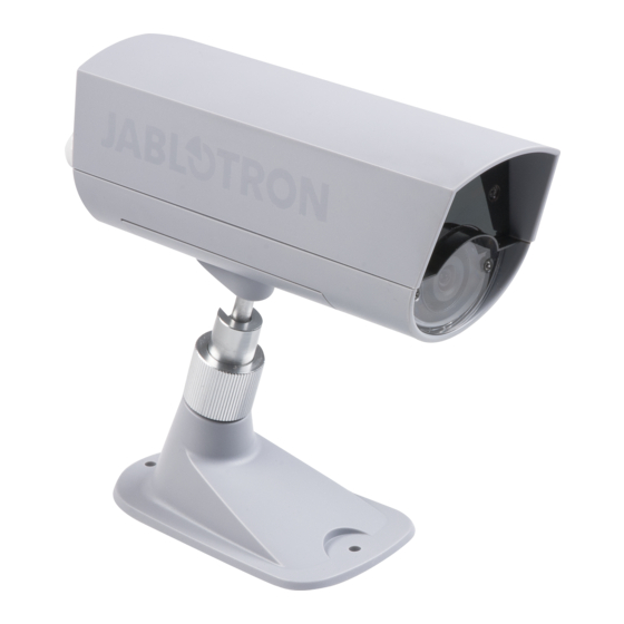
The JA-110C BUS photo verification camera
The JA-110C serves for taking one static picture of protected premises and
transfer to the JABLOTRON 100 control panel. The camera can take a photo
on command if it is required (by activation of a PG output by SMS or dialling in,
a requirement from the MyJABLOTRON app or by activation of any detector –
again via a PG output). This setting can be extended by the optional photo
buffering function. It splits taking the photos into pre-photos when the camera
regularly takes photos at a pre-defined frequency and saves them to its buffer
and also into post-photos when it takes the required number of photos after
activation.
The camera has built-in IR illumination for taking pictures in bad light
conditions and also a lighting intensity detector which can switch ON any PG
output (For instance to turn the external lighting on).
The camera also has a built-in tilt detector which protects against unwanted
manipulation. It occupies one position in the system.
The camera should be installed by a trained technician with a valid certificate
issued by an authorised distributor.
Installation
The camera can be installed outdoors or indoors. Although the camera has
a basic level of protection
against water for outdoor
installation we recommend
using
additional
cover
because of rain and snow
protection. If the front glass
is included in the additional
cover then IR illumination has
to be disabled. An external IR
illuminator can be used for
the
illumination
of
the
monitored area and can also
be switched on by the
function
"External
device
triggering". For simple setting
of
the
monitored
area
the camera is equipped with
a jointed holder (1).
Figure 1: 1 – Adjustable joint; 2 – camera lens;
3 – Indication LEDs and IR illumination
1.
Open
the
lower
camera
(by releasing 2 screws).
2.
The camera's jointed holder includes two
parts which split the adjustable joint (1).
Disassemble the holder by unscrewing
to get to its two parts (1).
3.
Install the lower part of the holder onto
the required place using two screws.
4.
On the rear part of the camera release
the bushing (4) and put the BUS cable
through the camera.
5.
Connect the BUS cable to the BUS
terminals (7).
Figure 2: 4 – gland for cables; 5 – mini USB;
6 – production code; 7 – BUS terminals;
8 – tamper contact
When connecting the detector to the system BUS,
always switch the power off.
6.
Proceed according to the control panel installation manual. Enrolling
the camera to the system and setting all parameters can only
be performed in Service mode.
Basic procedure:
a.
When the system has been turned on then the yellow LED (3) flashes
and it indicates the camera has not been enrolled to the system yet.
b.
Using F-Link software, select the required position in the Devices
window and launch enrolment mode by clicking on the Enroll option.
c.
Press the LEARN/TAMPER (8) button in the camera – the camera
is thus enrolled to the system on the required position and the yellow
LED indicator goes off.
7.
Close the camera's rear cover part first and then its front part –
confirm hearing the tamper contact clicking (when the cover
is closed from the side it could cause the tamper contact
to be switched on incorrectly (it slides down from the plastic edge)
and
in
the
Diagnostic
of the camera is visible.
Notes:
When the camera is placed out of protected area, for example in outdoor
environment, we strictly recommend using the JA-110T BUS isolator and put
it to BUS leg. This leg will protect the BUS against unwanted manipulation
(tampering).
The JA-110C BUS photo verification camera
cover
tab
the
activated
tamper
The camera is not equipped with an IR filter to get the best picture quality
at night which is why pictures taken during the day could be violet coloured.
The module can also be enrolled to the system by entering its production
code (6) in the F-Link software or using a bar code scanner. All numbers stated
under the bar code shall be entered (1400-00-0000-0001) or by option
"Scan/Add new BUS devices".
If the camera is enrolled as a first camera or a control panel is not connected
to an external mass storage area (http://img.jablotron.cz), F-Link shows
a dialogue window with a question: „Enable image transfer to the IMG server?".
We strictly recommend enabling this option with the agreement of the customer
and confirming this acceptance by recording it in the system service log with his
signature.
Caution: If the transmission is not enabled, photos will be saved
in the internal memory of the camera and the control panel. Then it is
impossible to send them to users´ cell phones and e-mails.
Setting the camera properties
The camera properties can be set by F-Link software (version 1.2.3 and
higher) – Devices tab. When at the camera position, use the Internal settings
option to open a dialog window where the following settings can be configured
(* default settings):
Activation PG for one photo: (*No) The function primarily serves to take
one photo when a selected PG (PGs) is triggered. The camera takes this photo
in LQ and HQ, but only LQ is sent. The HQ photo is temporarily stored in the
camera memory and sent when it is requested via the MyJABLOTRON app
or F-Link.
Note: The camera has a buffer for approximately 100 photos and it is also
the limitation for photos requested by the activation of a PG output to 3 photos
in 10 minutes.
Transferred to ARC as an alarm photo: (*Disabled) This option
determines if the captured photo will be taken as an alarm photo and sent
to the ARC.
Note: This option is visible if at least one activation PG is selected.
LED flashes every 30 s: (*Disabled)
By enabling this option the camera flashes every 30 s and then always when
a photo is taken. For outdoor detectors, sirens or any other verification devices
it is good to indicate they are active by regular warning flashes of the LED (they
can be taken as pre-detectors to detect any potential intrusion).
Photo buffering: (*Disabled) Activation of this option enables the function
of storing photos in the camera's buffer memory using the set interval.
If the memory is full, the oldest photos are deleted. By subsequently setting
"Photos before activation" and "Photos after activation" of the selected PG you
can store and send photos that can show what happened before or after
the entire PG activation.
Note: When setting the photo buffering function you should consider
the number of photos sent from the system (mentioned in the control panel
installation manual), especially if more cameras are installed in the system.
Transferred to ARC as an alarm photos: (*Disabled) This option
determines if the captured photos will be taken as alarm photos and whether
sent to the ARC.
Note: This option is visible when the parameter "Photo buffering" is enabled.
Taking a series of photos when PG triggered: (*No). This function
is primarily used to send a series of photos when a selected PG (or PGs)
is triggered. The number of saved photos before and after triggering
of the selected photos results from the subsequent setting. An activation photo
for Photo buffering is taken in LQ.
Photo interval (1-15 s.): (*5 s) It is used to set the frequency of photos
in a series. The optimum setting depends on the particular installation situation.
For instance: if the intruder is expected to come from the side or if the field
of view of the camera or the surrounding space is limited, a shorter time should
be set. The disadvantage is that the saved photos in the camera are
overwritten more quickly. If the camera covers a larger area and if the intruder
is expected to move towards the camera, a longer time should be set.
Note: We recommend you to test the camera setting in each situation
in the real environment (simulate the intruder). This is the only way to get
the product's optimal setting.
Pre-PG activation photos: (*Enabled) Disabling the option prevents
the saving and subsequent sending of photos taken before the triggering
of the selected PG (or PGs). Photos taken before activation of a PG are only
saved in LQ.
Post-PG activation photos: (*Enabled) Disabling this option prevents
the saving and subsequent sending of photos taken after activation
of the selected PG (or PGs). Photos taken after PG activation are saved in LQ
and HQ.
Number of taken photos (1-15 photos): (*1) This option serves
for setting the number of photos that are to be saved before/after triggering
of the selected PG. The total sum of saved photos may be max 15 + 1
activation (initiated by PG triggering). These 15 photos may include photos
contact
before and after activation of the PG in accordance with the customer´s
requirements or particular installation situation.
Number of sent photos (1-5 photos): (*1) This option serves for setting the
number of photos that are sent to the control panel and then through
an SMS or directly to the MyJABLOTRON portal. Always at least one photo
before the activation, the photo initiated by PG activation and a photo after
activation are sent.
1 / 2
MNT51105
Advertisement
Table of Contents

Related Manuals for jablotron JA-110C


Summary of Contents for jablotron JA-110C
- Page 1 The JA-110C BUS photo verification camera The JA-110C serves for taking one static picture of protected premises and The camera is not equipped with an IR filter to get the best picture quality transfer to the JABLOTRON 100 control panel. The camera can take a photo at night which is why pictures taken during the day could be violet coloured.
- Page 2 Installation recommendations Note: Sometimes it could happen that photos will be taken at the same time (duplication). This is determined by the camera’s internal algorithm. Several JA-110C cameras can be installed in the system. When several supplementary illumination: (*Auto)
Need help?
Do you have a question about the JA-110C and is the answer not in the manual?
Questions and answers