Table of Contents
Advertisement
OWNER'S
OPERATING
& INSTALLATION
MANUAL
CTX Electric Ovens
DZ33T/DZ26T-Series
© 2020 Middleby Marshall Inc.
is a registered trademark of Middleby Marshall, Inc. All rights reserved.
1
DZ33T/DZ26T-Series Electric Ovens: English
Combinations:
• Single Oven
• Double Oven (Two-Stack)
• Triple Oven (Three-Stack)
P/N 77267 rev A
Advertisement
Table of Contents

Related Manuals for Middleby Marshall CTX DZ33T Series


Summary of Contents for Middleby Marshall CTX DZ33T Series
- Page 1 OPERATING & INSTALLATION MANUAL Combinations: CTX Electric Ovens • Single Oven DZ33T/DZ26T-Series • Double Oven (Two-Stack) • Triple Oven (Three-Stack) © 2020 Middleby Marshall Inc. is a registered trademark of Middleby Marshall, Inc. All rights reserved. P/N 77267 rev A...
- Page 2 This manual must be kept in a prominent, easily reachable installing or servicing the equipment. location near the oven. Middleby Marshall suggests a service contract with a IMPORTANT Middleby Authorized Service Agent (ASA). An electrical wiring diagram for the oven is located inside DEFINITIONS the machinery compartment.
- Page 3 Seller shall not be liable for any prospective or lost profits of Buyer. for any prospective or lost profits of the buyer. This warranty is effective on Middleby Marshall equipment sold The foregoing shall be Seller’s sole and exclusive obligation and on, or after January 1st, 2007.
-
Page 4: Table Of Contents
Table of Contents SECTION 1 DESCRIPTION ..........5 III. STEP-BY-STEP OPERATION ....... 24 MODEL IDENTIFICATION ........5 A. Daily Startup Procedure ......24 II. DZ33T/DZ26T SERIES SPECIFICATIONS ..... 6 B. Daily Shutdown Procedure ......26 III. COMPONENT FUNCTION ........7 IV. -
Page 5: Section 1 Description
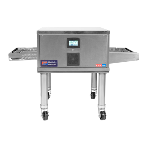
SECTION 1 DESCRIPTION SECTION 1 DESCRIPTION I. MODEL IDENTIFICATION CTX DZ33T/DZ26T conveyor ovens are designed to cook, bake, or broil in high volume with consistent quality results. The CTX oven may be used either as a single oven or stacked for use as double or triple ovens. -
Page 6: Dz33T/Dz26T Series Specifications
SECTION 1 DESCRIPTION II. DZ33T/DZ26T SERIES SPECIFICATIONS RECOMMENDED MINIMUM CLEARANCES Rear of Oven to Wall - 0" (0mm) Left Side of Oven to Wall - 4" (102mm) Right Side of Oven to Wall - 4" (102mm) DZ33T/DZ26T SERIES ELECTRICAL SPECIFICATIONS Model No. -
Page 7: Component Function
SECTION 1 DESCRIPTION Components Locations III. COMPONENT FUNCTION A. Touch Screen Oven Controller The touch screen controller controls all functions of the oven. The cooking temperatures can be set from 200°F to 900°F (93°C to 509°C). Cooking times (conveyor speed) can be set from 1:00 minute to 60:00 minutes The controller features several modes including: Manual Operation... -
Page 8: Infrared Heating Panels
SECTION 1 DESCRIPTION CTX Heat Zones B. Infrared Heating Panels Heating panels are positioned above and below the conveyor belt in the oven chamber (Figure 4). When energized these panels emit infrared long waves. These waves do not heat the air through which they pass. -
Page 9: Section 2 Installation
SECTION 2 INSTALLATION SECTION 2 INSTALLATION NOTE: All aspects of the oven installation, including WARNING placement, utility connections, ventilation Keep the appliance area free and clear of requirements, must conform with any applicable local, combustibles. national, or international codes. These codes supersede the requirements and guidelines provided WARNING in this manual. -
Page 10: Unloading, Dimensions, And Rough-In
I. UNLOADING, DIMENSIONS, AND C. Items for Stacking Oven ROUGH-IN The following items are required for stacking ovens: Your Middleby Marshall DZ33T/DZ26T-Series Oven is Quantity Description shipped partially assembled. It will arrive in a carton on 10' (305cm) 4-by-4 boards a crate. - Page 11 SECTION 2 INSTALLATION DZ33T Single Oven on a Base...
- Page 12 SECTION 2 INSTALLATION DZ33T Double-Stacked Oven on a Base DZ33T Triple-Stacked Oven on a Base...
- Page 13 SECTION 2 INSTALLATION DZ26T Single Oven on a Base...
- Page 14 SECTION 2 INSTALLATION DZ26T Double-Stacked Oven on a Base DZ26T Triple-Stacked Oven on a Base...
- Page 15 SECTION 2 INSTALLATION DZ33T Single Oven Stand Parts Item Qty. Part Number Description 67880 INSUL, BASE PART A 67881 INSUL, BASE PART C 67882 INSUL, BASE PART B PARTS LISTED ABOVE ARE FROM 69978 KIT, DZ33T INSULATION 67884 WLDMT. BASE DZ33 67614 PANEL, TOP 66948...
- Page 16 SECTION 2 INSTALLATION DZ26T Single Oven Stand Parts Item Qty. Part Number Description 75219 INSUL, BASE PART A 75220 INSUL, BASE PART C 75221 INSUL, BASE PART B PARTS LISTED ABOVE ARE FROM 75218 KIT, DZ26T INSULATION 75213 WLDMT. BASE DZ33 73403 PANEL, TOP 66948...
-
Page 17: Base Section Assembly
SECTION 2 INSTALLATION Oven Stand Parts D. Base Section Assembly sticking out of the oven equally on both sides. One of the boards should be placed to the rear of the 1. Locate the carton containing the oven base. oven and the other in the front of the oven. See Remove and inventory the contents. -
Page 18: Stacking And Mounting Two Ovens
SECTION 2 INSTALLATION NOTICE NOTICE Dispose of the skid in accordance with local Lift the oven with the 10' (305cm) 4-by-4 boards running through the oven only. DO NOT lift the regulations. oven by the conveyor. Damage WILL result. 7. Lift the oven high enough to position the stand under it. - Page 19 SECTION 2 INSTALLATION NOTICE NOTICE Make sure protective plastic film is removed from Make sure protective plastic film is removed from draft curtains before installation. exit shelves before installation. 1. Draft Curtains, stainless steel (2 per oven). These 2. Exit Shelves, stainless steel (2 per oven). These mount above the conveyor at the ends of the shelves mount in cantilever fashion at the exit and cooking chamber.
-
Page 20: Ventilation Guidelines
SECTION 2 INSTALLATION UTILITY ROUGH-IN DIMENSIONS AND POSITIONING FOR DZ33T/DZ26T-SERIES OVEN WARNING Do not use conduit for ground connection. CAUTION It is recommended that the oven be placed under a ventilation hood for adequate air supply and ventilation. IMPORTANT Electric supply to be provided by customer. CIRCUIT BREAKER Separate circuit breaker with lockout/tagout electrical shutoff for each oven. -
Page 21: Electrical Connection Information For Dz33T/Dz26T-Series Ovens
SECTION 2 INSTALLATION III. ELECTRICAL CONNECTION INFORMATION FOR DZ33T/DZ26T- SERIES OVENS WARNING Authorized supplier personnel normally accomplish the connections for the ventilation system and electric supply, as arranged by the customer. Following these connections, the factory-authorized installer can perform the initial start-up of the oven. - Page 22 SECTION 2 INSTALLATION NOTES...
-
Page 23: Section 3 Operation
SECTION 3 OPERATION SECTION 3 OPERATION I. CONTROL FUNCTIONS DZ33T/DZ26T-Series Oven Control Functions B. Circuit Breakers WARNING Possibility of injury from rotating parts and 3 amp circuit breakers provide overload protection for electric shock. the control circuit. Never disassemble or clean the oven with the C. -
Page 24: Step-By-Step Operation
SECTION 3 OPERATION Control Panel III. STEP-BY-STEP OPERATION Touch the large onscreen on/off button. The screen shows either the Manual Mode touch A. Daily Startup Procedure screen or the Preset Mode touch screen, depending on the mode the oven was in when last 1. - Page 25 SECTION 3 OPERATION Operating in Preset Mode: NOTE: If the Preset Mode touch screen shows the preset you want to use and “Ready” appears in the upper right, the oven has heated to the displayed temperatures and the conveyor is running at the displayed speed. The oven is ready to use.
-
Page 26: Daily Shutdown Procedure
SECTION 3 OPERATION 5. When the Set Temperature screen appears, enter a new temperature (for example, 7 - 0 - 0). The new temperature appears in the green highlighted area of the Set Temperature screen. 6. In the lower right area of the screen, choose if you want to Save the new temperature to Left Only or Both. -
Page 27: Touch Screen Adjustments
SECTION 3 OPERATION IV. TOUCH SCREEN ADJUSTMENTS A. Setup Mode Entering the Setup Mode: 1. From the Manual or Preset main screen, touch the Setup button. The Passcode screen appears. 2. Enter the passcode 1 - 3 - 9 - 7. The number in the green highlighted area changes to 1397, then the Settings screen appears. - Page 28 SECTION 3 OPERATION Changing Temperature Unit: On the Settings screen, touch the Temp. Unit button to change between °F and °C. Changing Language: This feature is not operational at this time. Changing Volume: The Volume button allows the user to change the volume of the audible interface when buttons are touched.
- Page 29 SECTION 3 OPERATION Making Changes to a Preset: 1. On the Settings screen, touch the Presets button. The Preset Change screen appears.
- Page 30 SECTION 3 OPERATION 2. Touch the preset you want to change (for example, Preset 1). The chosen preset screen appears. 3. To change the name of the preset to a product, touch the Name button. A keyboard screen appears. 4. Enter the new name using the keyboard (for example, Chicken Breast).
- Page 31 SECTION 3 OPERATION 8. In the lower right area of the screen, choose if you want to Save the new temperature to Left Only or Both. (If you had started with a right setting, the choice would be Right Only or Both.) The chosen preset screen reappears with the new temperature settings.
-
Page 32: Standby Mode
SECTION 3 OPERATION 15. Press the Back button one more time to return to the Settings screen. NOTE: To change another Preset, touch the Preset button from the Settings screen and start the process again. Exiting the Setup Mode: From the Settings screen, touch the Back button to return to the Preset Mode with the preset changed and saved. -
Page 33: Info Mode
SECTION 3 OPERATION C. Info Mode The Info Mode is a feature which shows the actual temperatures and belt speeds onscreen while operating. Viewing Information in Manual Mode: To view the actual temperatures and belt speeds in Manual Mode, touch the Info. button. The actual values appear in a smaller size above the settings. -
Page 34: Quick Reference: Faults
SECTION 3 OPERATION V. QUICK REFERENCE: FAULTS Fault messages are only displayed on the main screens of Manual Mode and Preset Mode. If a message is displayed, touch the screen to acknowledge the fault. MESSAGE DISPLAYED EXPLANATION CORRECTIVE ACTION IO_COMM_LOST* IO Communications Fault Acknowledge the fault. - Page 35 SECTION 3 OPERATION CONTROL High Temp: Control Compartment Check cooling proper COMPARTMENT HIGH operation and cleanliness. Clean the temperature control necessary (see TEMP compartment has exceeded the set limit for MAINTENANCE – WEEKLY). more than 5 seconds. The oven beeps, the Acknowledge the fault.
-
Page 36: Cooking In A Ctx Oven
SECTION 3 OPERATION VI. COOKING IN A CTX OVEN NOTE: Sometimes an increase in temperature may require a corresponding decrease in cooking time. A. Cooking Trials Conversely a decrease in temperature may require a corresponding increase in cooking time. The purpose of conducting cooking trials is to determine the exact temperature settings and cooking After evaluating the results, make the indicated time needed to produce best results with your specific... - Page 37 SECTION 3 OPERATION Record Time and Temp Table Product Zone Temperatures Cook Time Pan Type and Amount State Min. Size Weight or Entrance Exit Count Top / Bott Top / Bott...
- Page 38 SECTION 3 OPERATION NOTES...
-
Page 39: Section 4 Maintenance
NOTICE ANY replacement parts that require access to the interior of the oven may ONLY be replaced by a Middleby Marshall Authorized Service Agent. It is also strongly recommended that the 3-Month Maintenance and 6-Month Maintenance procedures in this section be performed ONLY by a Middleby Marshall Authorized Service Agent. - Page 40 SECTION 4 MAINTENANCE 3. Dry and re-install the 6. Wipe with a towel with heat curtain. general purpose cleaner send through dishwasher (optional). Dry and re- install. 4. Remove any crumbs with wire brush. 7. Remove the exit tray, wipe with a clean towel 5.
- Page 41 SECTION 4 MAINTENANCE 9. Remove fan filter, rinse with cold water and place back on when dry. 10. Wipe the top, front and sides with a clean towel with general purpose cleaner.
-
Page 42: Maintenance - Weekly
SECTION 4 MAINTENANCE II. MAINTENANCE - WEEKLY 2. Touch “Yes” to confirm. The oven will begin to count time up until the oven attains a temperature Clean the filter of the cooling fan. of 900°F (482°C) as shown in Figure 20. The 1-hour timer will then begin to count down to zero. -
Page 43: Maintenance - Every 3 Months
Replacement parts for these kits can be purchased from your Middleby Marshall Authorized Parts Distributor. B. Ventilation Check that the air circulation throughout the oven is... - Page 44 SECTION 4 MAINTENANCE DZ33T-SERIES ELECTRIC OVEN KEY SPARE PARTS KIT (Figure 22) ITEM PART NO. DESCRIPTION DZ33T, 208/240V DZ33T, 380/415V 77174 Filter, Magnetic Fan M9616 Fan, Cooling 24VDC 74916 Switch, Schurter 3-101-431 74902 Display, NCC Touch Screen 67975 Contactor 4 pole 67857 Solid state relay 45036...
- Page 45 SECTION 4 MAINTENANCE DZ26T-SERIES ELECTRIC OVEN KEY SPARE PARTS KIT (Figure 23) ITEM PART NO. DESCRIPTION DZ26T, 208/240V DZ26T, 380V 77174 Filter, Magnetic Fan M9616 Fan, Cooling 24VDC 74916 Switch, Schurter 3-101-431 74902 Display, NCC Touch Screen 76957 Contactor, Finder Type 22.34 67857 Relay, 240V 75A Solid State 45036...
- Page 46 SECTION 4 MAINTENANCE NOTES...
-
Page 47: Section 5 Troubleshooting
SECTION 5 TROUBLESHOOTING SECTION 5 TROUBLESHOOTING SYMPTOM PROBLEM SOLUTION Conveyor belt stops completely 1. Check for objects jammed in • Check to see if drive roller is or intermittently. conveyor and remove. turning. 2. Turn oven off, reset the circuit breaker, and turn oven on. - Page 48 SECTION 5 TROUBLESHOOTING NOTES...
-
Page 49: Section 6 Electrical Schematics
SECTION 6 ELECTRICAL SCHEMATICS SECTION 6 ELECTRICAL SCHEMATICS Wiring Diagram, DZ33T, E208-240V 3PH • 77316 REV B... - Page 50 SECTION 6 ELECTRICAL SCHEMATICS...
- Page 51 SECTION 6 ELECTRICAL SCHEMATICS...
- Page 52 SECTION 6 ELECTRICAL SCHEMATICS Wiring Diagram, DZ33T, 380V 3PH CE • 77318 REV B...
- Page 53 SECTION 6 ELECTRICAL SCHEMATICS...
- Page 54 SECTION 6 ELECTRICAL SCHEMATICS Wiring Diagram, DZ33T, 230V 1PH CE • 77320 REV B...
- Page 55 SECTION 6 ELECTRICAL SCHEMATICS...
- Page 56 SECTION 6 ELECTRICAL SCHEMATICS Wiring Diagram, DZ33T, 380/416V 3PH • 77322 REV B...
- Page 57 SECTION 6 ELECTRICAL SCHEMATICS...
- Page 58 SECTION 6 ELECTRICAL SCHEMATICS Wiring Diagram, DZ26T, 208/240 3PH • 75324 REV B...
- Page 59 SECTION 6 ELECTRICAL SCHEMATICS Wiring Diagram, DZ26T, 380V 3PH CE • 76982 REV B...
- Page 60 SECTION 6 ELECTRICAL SCHEMATICS Wiring Diagram, DZ26T, 230V 1PH CE • 76983 REV B...
- Page 61 SECTION 6 ELECTRICAL SCHEMATICS Wiring Diagram, DZ26T, 380/416V 3PH • 76984 REV B...
- Page 62 NOTICE During the warranty period, ALL parts replacement and servicing should be performed by your Middleby Marshall Authorized Service Agent. Service that is performed by parties other than your Middleby Marshall Authorized Service Agent may void your warranty.
Need help?
Do you have a question about the CTX DZ33T Series and is the answer not in the manual?
Questions and answers