Table of Contents
Advertisement
Quick Links
(Multi Channel System for Process Industry)
PWR
Com
6
5
4
3
2
1
0
Act
FLINTEC
www.flintec.com
Manual MCS-64
MCS-64
Manual MCS-64 with CANbus
C 0 1 2 3 C
C 0 1 2 3 C
Logic out
Logic in
PWR
PWR
Com
Com
In 0
In 0
In 1
In 1
In 2
In 2
In 3
In 3
Out 0
Out 0
Out 1
Out 1
Out 2
Out 2
BC
Out 3
Out 3
470uF
Err
Err
+
HP
Load
Cells
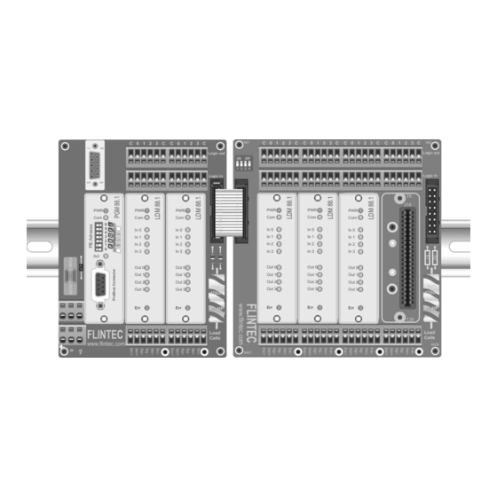
Example of MCS-64 with 5 channels and Profibus-Gateway
Document no. G164-Rev4-GB
www.flintec.com
Mt1
C 0 1 2 3 C
C 0 1 2 3 C
ON
DIP
1 2 3 4
PWR
PWR
Com
Com
In 0
In 0
In 1
In 1
In 2
In 2
In 3
In 3
Out 0
Out 0
Out 1
Out 1
Out 2
Out 2
Out 3
Out 3
Err
Err
Mt27
C 0 1 2 3 C
C 0 1 2 3 C
Mt2
Logic out
Logic in
T6
J14
PWR
Com
In 0
In 1
In 2
In 3
Out 0
Out 1
Out 2
BC
Out 3
470uF
Err
+
HP
T26
Load
Cells
Mt28
Page 1
Advertisement
Table of Contents

Related Manuals for Flintec MCS-64


Summary of Contents for Flintec MCS-64
- Page 1 Out 2 Out 2 Out 3 Out 3 Out 3 Out 3 Out 3 470uF 470uF FLINTEC Load Load Cells Cells www.flintec.com Mt28 Mt27 Example of MCS-64 with 5 channels and Profibus-Gateway Document no. G164-Rev4-GB www.flintec.com Manual MCS-64 Page 1...
- Page 2 Components of MCS-64 in overview LDM 88.1 CGM 85,1 Base Board MB 89.1 In 0 In 1 RS 232 LDM 88.1 In 2 Load Cell Service-Port In 3 Fieldbus Gateway Out 0 Out 1 LDM 88.1 Out 2 Load Cell - Profibus (PGM 68.1)
- Page 3 12 ... 24 V DC ±10 %, < 60 mA,(reversed voltage, burst and ESD protected) Power consumption 1,5 W max. CE 73/23/EEC; 93/98/EEC and 89/336/EEC Computer interface via RS232C, 115 200 Baud Service Port MB 89.1 Vibration withstands 1.0 G operational; 2.5 G non-operational Manual MCS-64 Page 3...
-
Page 4: Table Of Contents
4.11 Save calibration, setup and setpoint parameters Commands – CS, WP, SS ...49 4.12 Filling Commands – PD1 to PD21, DI, SC, AC, GD, DT, SD......50 4.13 Loss in Weight Commands – PL1 to PL5, LC, LI, GF, GR, GM.......51 4.14 Speed Estimation Multi-Channel System MCS-64 ...........52 Page Manual MSC-64... - Page 5 5 MCS-64 Components and Configuration ..........53 Base Board MB 89.1 for 1 Gateway and 2 LDM 88.x ..........53 Extension Board MB 89.2 for 2 LDM 88.x.............. 54 Extension Board MB 89.3 for 4 LDM 88.x.............. 55 Extension Board MB 89.4 for 8 LDM 88.x.............. 56 Address setup guide extension boards for 1 –...
-
Page 6: Introduction
This document describes the system design for a CANopen Gateway (CGM85) and up to 64 Load Cell Digitizing Module (LDM88.x) using the Flintec backplane system. It describes the functionality of the backplane, the protocol used on the backplane and the CANopen profile used to access the LDM88 modules via the CGM85 Gateway. -
Page 7: System Detailed Design
At a very low priority the Gateway looks for backplane modules that aren’t recorded as active, in order to re-establish communication with modules that may have been restarted to recover from failure. The Gateway always informs the CAN controller when a module fails, or comes back online. Manual MCS-64 Page 7... -
Page 8: Canopen
2.3 CANopen The CANopen Gateway follows the CAN2.0B recommendations. It receives both 11-bit identifiers, and tolerates 29-bit identifiers. It only transmits 11-bit identifiers. The Gateway is always quiet on the CANbus until the NMT Start command is received, except for the very first ‘node guard’ message. When started, the TPDO1 is used to send current status information. -
Page 9: Canopen Profile
LDM has acknowledged the command. “resp” is a modulo-4 counter that increments when a command has been processed (and a result can be fetched). If a SDO has been received, it indicates when the Gateway has finished processing the SDO. Manual MCS-64 Page 9... -
Page 10: Communication Profile
The CANopen SDOs is a confirmed service, and overrun does not occur if the CAN controller only communicates with the Gateway in the PRE-OPERATIONAL state. When a SDO has been received by the controller no further communication takes place until the service has been acknowledged (or a timeout occurs). - Page 11 Producer Heartbeat time in ms. If index 1017h is non-zero the Heartbeat protocol is used, otherwise the Node-guard protocol is used. 1018 Identity Object Number of entries Vendor ID UI32 Vendor ID Product Code UI32 Product Code Revision Number UI32 Revision Number Serial Number UI32 Serial Number Manual MCS-64 Page 11...
- Page 12 Bit1 Bit0 Cmd: 1602 Number of mapped Mapping parameters of the 3 Receive- PDO (disabled) Entries in Rx PDO 3 1603 Number of mapped Mapping parameters of the 4 Receive-PDO (disabled) Entries in Rx PDO 4 Manual MCS-64 Page 12...
- Page 13 COB-ID UI32 80000480H + Determined using the CANopen minimum system ID assignment procedure. NodeID Asynchronous communication. Transmission type Transmit inhibit time of PDO in 100 µs steps. Inhibit Time UI16 (not used, will not be transmitted) Manual MCS-64 Page 13...
- Page 14 20020308H Gateway Status 1A02 Number of mapped Mapping parameters of the 3 Transmit- PDO (disabled) Entries in Tx PDO 3 1A03 Number of mapped Mapping parameters of the 4 Transmit-PDO (disabled) Entries in Tx PDO 4 Manual MCS-64 Page 14...
- Page 15 Number of objects in the dosed result. Object UI16 Module Status Object Module ID [0...63]. The module that finished a filling cycle. Object Gateway Status 2003 Number of entries Number of bytes in hardware identification array. 1..16 Hardware ID bytes Manual MCS-64 Page 15...
- Page 16 CAN parameters (changes take effect after restart) CAN speed 1=1Mbit; 2=500Kbit; 3=250Kbit; 4=125Kbit; 5=50Kbit. CAN address DIP-SW The CANopen address. (DIP-SW on MCS-64) LDM Scan end Last LDM module to include in the scan (default: 16 LDM modules). Manual MCS-64 Page 16...
- Page 17 Zero track (TAC protected) Parameter ∆ Time 21FF Number of entries. Number of general parameters. As for 2100-2163 As for 2100 – 213F, except this is WRITE ONLY and the settings are broadcasted to all LDMs. Manual MCS-64 Page 17...
- Page 18 Tare interval – the number of fillings per tare measurements Parameter Bad rupture blanking 22FF Number of entries. Number of filling parameters. As for 2200-2263 As for 2200 – 223F, except this is WRITE ONLY and the settings are broadcasted to all LDMs. Manual MCS-64 Page 18...
- Page 19 Display step size Display step size (TAC protect) 23FF Number of entries. Number of calibration parameters. As for 2300-233F As for 2300 – 233F, except this is WRITE ONLY and the settings are broadcasted to all LDMs. Manual MCS-64 Page 19...
- Page 20 The High byte has the following interpretation: 00= Idle 01= Waiting for trigger(2 trigger) 02= Bottle on, calculating tare 03= Pre-fill 04= Main Filling 05= Fine Filling 06= In-flight delay 07= Post fill calculations 08= Post Filling Manual MCS-64 Page 20...
- Page 21 Delta time Max Retriggers Count Max Retriggers Count 25FF Number of entries. Number of Check-Weigher parameters. As for 2500-253F As for 2500 – 253F, except this is WRITE ONLY and the settings are broadcasted to all LDMs. Manual MCS-64 Page 21...
- Page 22 Set-point 3 source Set-point 4 Set-point 4 source 0..63 28FF Number of entries. Number of Set-point parameters As for 2800-283F As for 2800 – 283F, except this is WRITE ONLY and the settings are broadcasted to all LDMs Manual MCS-64 Page 22...
- Page 23 1000000 d/sec, 1000000 d/min, 1000000 d/hour. 2BFF Number of entries. Number of mass flow parameters. As for 2B00-2B3F As for 2B00 – 2B3F, except this is WRITE ONLY and the settings are broadcasted to all LDMs. Manual MCS-64 Page 23...
- Page 24 These values are the floating-point representation of the weight as they are Net Weight REAL32 transmitted in the PDO1(tx). Tare REAL32 Index 6403 is a replica of index 2000. Dosed weight REAL32 Dosed tare REAL32 Average weight REAL32 Manual MCS-64 Page 24...
- Page 25 Notices: Manual MCS-64 Page 25...
-
Page 26: Quick Start Guide
3.4 Quick Start Guide 3.4.1 Process data objects TPDO1 Weight values are available at all times (see page 9) The following table shows the information of TPDO1: 32 bit 16 Bit 8 bits 8 Bit Gateway Weight Module Status Module number State Default : net weight. -
Page 27: Service Data Objects
Are only available on request See tables 3.3 Object Directory Can be used for complete setup of the System MCS-64 via CANbus master, e.g.: - Filter setting channel 1: Index 2100, Subindex 4 - Filter Mode setting channel 3: Index 2102, Subindex 9 Can be used to get information regarding all the commands available, e.g.:... -
Page 28: Commands
4.12 Filling Commands – PD1 to PD21, DI, SC, AC, GD, DT, SD........50 4.13 Loss in Weight Commands – PL1 to PL5, LC, LI, GF, GR, GM......51 4.14 Speed Estimation Multi-Channel System MCS-64 ..........52 Page Manual MSC-64... -
Page 29: System Diagnosis Commands - Id, Iv, Is
System diagnosis Commands – ID, IV, IS Use these commands to get type, firmware version or device status of System MCS-64. These commands are sent without parameters. Request of device identity [ 2900sub08 ] Master (PC / PLC) sends Devices responds D:8813 The response to this request gives the actual identity of the active device. -
Page 30: Calibration Commands - Ce, Cm, Ci, Ds, Dp, Cz, Cg Az, Ag, Zt, Fd, Cs
4.2 Calibration Commands – CE, CM, CI, DS, DP, CZ, CG AZ, AG, ZT, FD, CS Note: TAC represents Traceable Access Code (calibration counter). TAC counter reading [ 2300sub03 ] With this command you get the TAC counter reading or you can enable a calibration sequence. - Page 31 For calibration an input signal near the display maximum (CM) will give the best system performance. The minimum calibration load of at least 20% is recommended. Factory default: 200000 d = 2.000 mV/V input signal = 20 kg Manual MCS-64 Page 31...
- Page 32 Absolute zero point calibration [ 2300sub02 ] The command AZ is used as reference point for all weight calculations and will setup in mV/V. Permitted values are ± 32000 (= ± 3.2000 mV/V). Master (PC / PLC) sends Device responds Result Request : Z+0.0005...
- Page 33 The CS command saves all of the calibration group values, as set by CZ, CG, CM, DS, DP and ZT. The command returns ERR and has no updating action unless it is preceded by the CE_XXXXX. Manual MCS-64 Page 33...
-
Page 34: Motion Detection Commands - Nr, Nt
4.3 Motion detection Commands – NR, NT The motion detection facility provides a means of disabling certain functions whenever a condition of instability, or “motion”, is detected. The “no-motion”, or “stable” condition is achieved whenever the signal is steady for the period of time set by NT, during which it cannot fluctuate by more than NR increments.The stable condition activates the relevant bit of responses to “Info Status”... -
Page 35: Filter Setting Commands - Fm, Fl, Ur
Mode 0 Characteristic (IIR-Filter) Settling time to 3dB Cut-off Damping Output-rate* 0.1% frequency @300Hz (samples/s) (ms) (Hz) (dB) no filtering 1923 3847 0.25 * Output-rate = 600/2 samples/s ** Antialiasing filter 17 Hz @ 60 dB/dec Manual MCS-64 Page 35... - Page 36 Mode 1 Characteristic (FIR-Filter) Settling time 3 dB Cut- 20 dB 40 dB Damping in Output rate Stopband damping at damping at to 0.1% max. frequency frequency stopband (Hz) (ms) (Hz) (Hz) (Hz) (dB) (samples/s) no filtering 19.7 >90 >80 >90 >40 >90...
-
Page 37: Set Zero/Tare And Reset Zero/Tare Commands - Sz, Rz, St, Rt
Zero point CZ active again The LDM88.x responds to the RZ command with either OK or ERR. If OK is returned then the “zero action performed” bit in the Device Status (IS) response will be set to “0”. Manual MCS-64 Page 37... - Page 38 Set Tare RPDO1 [ 00 08 ] This command will activate the net weighing function by storing the current weight value as a tare. The weight signal must be “stable” within the limits set by NR (No Motion Range) and NT (No Motion Time) commands for the “signal stable”...
-
Page 39: Output Commands - Gg, Gn, Gt, Gs
Master (PC / PLC) sends Device responds Result AD-value = 125.785 d S+125785 For service applications, it is helpful to note the GS values for the “no-load” or “zero” output and when the “calibration load” is applied. Manual MCS-64 Page 39... -
Page 40: Setpoint Commands - Sn, Hn, An
4.7 Setpoint Commands - Sn, Hn, An The LDM88.x has 4 setpoints where the status is dependent on the weight value. Each of them can be assigned as an independent setpoint value (Sn) with a corresponding hysteresis/switch action (Hn) and base (An – switch on the gross or the net weight). Setpoint 1 [ 2600sub01 ] Request / Setting... - Page 41 Similarly to read or set the setpoint 1 base, use A2 instead of A1 etc. ( 2800sub02 The MCS-64 transmits one TPDO2 every time a setpoint changes state. The weight sent in the TPDO2 is the weight that caused the TPDO2 to be transmitted, Net or Gross as selected for the actual setpoint.
-
Page 42: Trigger Commands - Sd, Mt, Ga, Te, Tr, Tl
4.8 Trigger Commands – SD, MT, GA, TE, TR, TL Remark: These commands are only available in firmware 88.183 (see time diagram page 44); the TR command is also available in the 88.184 firmware. Note: All setups should be stored with the WP command before power off. Start Delay 0 …... - Page 43 88.183) or to start a filling process (firmware 88.184) [ Special returned values are: - 99999 = trigged measurement in progress - 88888 = Re-Trigger in progress - 99996 = Tried to change Tare or Zero before end of measurement ] Manual MCS-64 Page 43...
- Page 44 Page Manual MSC-64...
-
Page 45: Trigger Special Commands- Rw, Tt, Ts, Dt, Tw, Ti, Ht
Request: TS=00000 T+00000 Setting: TT=480d TS_480 Factory default: 00000 [ The Re-Trigger can also be stopped with RPDO2 [00 01] for LDM #1, RPDO2 [01 01] for LDM #2, RPDO2 [02 01] for LDM #3 etc.. ] Manual MCS-64 Page 45... - Page 46 Delta Time [ 2500sub0B ] Set the Delta Time in milliseconds [ms]. During MT and TT timeframes "sub-averages" will be calculated by the system over the time DT. If a sub-average is outside the re-trigger window, the re-trigger function is automatic started. Master (PC / PLC) sends Device responds Result...
-
Page 47: Communication Setup Commands - Ad & Br
4.10 Communication setup Commands – AD & BR NOTE: These settings will only take effect after a power on reset (remember to store the settings using the WP command before turning the power off.) [2004sub03] Device address setup / request [ 2007sub02 ] It is possible to set the network address of the device using the AD command. -
Page 48: Save Calibration, Setup And Setpoint Parameters Commands - Cs, Wp, Ss
[ 2004sub05 ] With this command the settings of the setpoints (Sn), the “setpoint hysteresis” (Hn) and the “setpoint action” (An) will be saved in the EEPROM. Master (PC / PLC) sends Device responds Result Parameter saved Error Manual MCS-64 Page 49... -
Page 49: Filling Commands - Pd1 To Pd21, Di, Sc, Ac, Gd, Dt, Sd
4.12 Filling Commands – PD1 to PD21, DI, SC, AC, GD, DT, SD Remark: These commands are only available in firmware 88.184. Note: All setups should be stored with the SD command before power off. A separate description of these commands is availble as pdf-file. Please contact germany@flintec.net. Page Manual MSC-64... -
Page 50: Loss In Weight Commands - Pl1 To Pl5, Lc, Li, Gf, Gr, Gm
4.13 Loss in Weight Commands – PL1 to PL5, LC, LI, GF, GR, GM Remark: These commands are only available in firmware 88.185. Note: All setups should be stored with the SL command before power off. A separate description of these commands is availble as pdf-file. Please contact germany@flintec.net. Manual MCS-64 Page 51... -
Page 51: Speed Estimation Multi-Channel System Mcs-64
Speed Estimation Multi-Channel System MCS-64 4.14 Gateway CANopen CGM 85.1 No. of Channels Transfer Rate per Channel Remark 40 Measurements/sec * * new firmware in gateway required 20 Measurements/sec * * new firmware in gateway required 10 Measurements/sec 5 Measurements/sec This speed estimation is for example valid for gross / net weight. -
Page 52: Mcs-64 Components And Configuration
5 MCS-64 Components and Configuration These pages describe the MCS-64 pcbs and the address setups for the expansion boards. 5.1 Base Board MB 89.1 for 1 Gateway and 2 LDM 88.x C 0 1 2 3 C C 0 1 2 3 C... -
Page 53: Extension Board Mb 89.2 For 2 Ldm 88.X
5.2 Extension Board MB 89.2 for 2 LDM 88.x Page Manual MSC-64... - Page 54 C 0 1 2 3 C C 0 1 2 3 C C 0 1 2 3 C Logic out 4 DO terminal blocks Logic in 4 DI terminal blocks 470uF 4 load cell terminal blocks Load Cells MT28 MT27 Manual MCS-64 Page 55...
-
Page 55: Extension Board Mb 89.4 For 8 Ldm 88.X
5.4 Extension Board MB 89.4 for 8 LDM 88.x Exc- Sen- Sig- Sig+ Sen+ Exc+ Exc- Sen- Sig- Sig+ Sen+ Exc+ Exc- Sen- Sig- Sig+ Sen+ Exc+ Exc- Sen- Sig- Sig+ Sen+ Exc+ Exc- Sen- Sig- Sig+ Sen+ Exc+ Exc- Sen- Sig- Sig+... -
Page 56: Address Setup Guide Extension Boards For 1 - 16 Channels
MB 89.3 MB 89.2 12 ch. MB 89.1 MB 89.2 MB 89.3 MB 89.3 14 ch. MB 89.1 MB 89.2 MB 89.3 MB 89.2 MB 89.3 16 ch. MB 89.1 MB 89.2 MB 89.3 MB 89.4 Manual MCS-64 Page 57... -
Page 57: Address Setup Guide Extension Boards For Up To 32 Channels
5.6 Address setup guide extension boards for up to 32 channels DIP switch setting see table below 18 ch. MB 89.2 MB 89.2 MB 89.1 MB 89.3 MB 89.4 20 ch. MB 89.1 MB 89.2 MB 89.3 MB 89.4 MB 89.3 22 ch. -
Page 58: Example Check Weigher Wiring
5.7 Example Check Weigher Wiring Service Port RS 232C Manual MCS-64 Page 59... -
Page 59: Example Liquid Filling Wiring
5.8 Example Liquid Filling Wiring Service Port RS 232C Page Manual MSC-64... -
Page 60: Ldm 88.1 - Digital Input / Digital Output
Output 4 3 Output 4 3 Common C Common C Inputs LDM 88.1 opto-isolated 10 ... 30 V DC, max. 3 mA Input 1 0 Input 2 1 Input 3 2 Input 4 3 Common C Manual MCS-64 Page 61... -
Page 61: Firmware Versions
5.10 Firmware Versions LDM 88.183 for check weighing and dosing/filling of non fluid products LDM 88.184 for dosing/filling of fluids LDM 88.185 for mass flow, trend and totalizing of fluids/powder 5.11 Appendix For CANbus communication via PC (Win2000/XP) with USB-port you can use: PCAN-USB-Adapter Supplier: PEAK-System Technik GmbH, D-64293 Darmstadt article no. - Page 62 CENELEC EN 60742 Safety regulations: EN 55011 and EN 61000. Electromagnetic Compatibility: and further requirements as listed in the order specifications as agreed upon. Meckesheim, April 20, 2007 Signature: i.V. Gisbert Greulich Being the responsible person employed and appointed by Flintec GmbH...
Need help?
Do you have a question about the MCS-64 and is the answer not in the manual?
Questions and answers