Table of Contents
Advertisement
Quick Links
JSC METALNA INDUSTRIJA VRANJE
Radnička St. No. 1
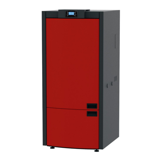
PELLET BOILER
COMMO COMPACT 32
Installation, Operation and Maintenance Manual
This product meets the requirements of the Ecodesign Directive in terms of efficiency and air pollution level, in order to
contribute to the reduction of energy consumption and negative environmental impact.
ENG_V.2.0
1612039
Advertisement
Table of Contents

Related Manuals for Alfa Plam COMMO COMPACT 32

Summary of Contents for Alfa Plam COMMO COMPACT 32
- Page 1 JSC METALNA INDUSTRIJA VRANJE Radnička St. No. 1 PELLET BOILER COMMO COMPACT 32 Installation, Operation and Maintenance Manual This product meets the requirements of the Ecodesign Directive in terms of efficiency and air pollution level, in order to contribute to the reduction of energy consumption and negative environmental impact.
- Page 2 Thank you for purchasing Commo Compact 32 boiler. Please read the entire Operation Manual carefully before installing and using your Commo Compact 32 boiler. Heating devices (hereinafter referred to as "pellet boiler s" or "boiler s") produced by company “Alfa Plam JSC” are designed, manufactured and tested in accordance with the requirements of the applicable European Safety Standards Directives.
-
Page 3: Table Of Contents
Possible Problems and Solutions ..................... 22 INFORMATION ON THE DISPOSAL AND DISASSEMBLY OF THE BOILER ..........24 TECHNICAL CHARACTERISTICS OF COMMO COMPACT 32 PELLET BOILER..........24 DIMENSIONS OF COMMO CONTACT 32 BOILER ..................26 HYDRAULIC INSTALLATIONS DIAGRAM OF COMMO CONTACT 32 PELLET BOILER ......... 26... - Page 4 Pellet boiler hydraulic installation diagram (radiator and floor heating) ..........27 Pellet boiler hydraulic installation diagram (accumulation tank) ............28...
-
Page 5: Purpose Of This Manual
RESPONSIBILITY OF THE MANUFACTURER By delivering this manual, “Alfa Plam JSC” shall not accept any legal or criminal liability, either direct or indirect, for: Accidents and/or damage occurred due to the non-observance of the standards and specifications stated in this Manual, Accidents and/or damage occurred due to the improper operation or use of the boiler by the user, Accidents and/or damage occurred due to any modifications and repairs not approved by “Alfa Plam JSC”,... -
Page 6: Installation
Whether the room in which the boiler is being installed is appropriate, i.e. minimum size of the room in which the boiler is to be installed, Compliance with the flue gas regulations set forth in the instructions supplied by the manufacturer of the heating device ... -
Page 7: Air Supply
Como Compact 32 Boiler alarm may be activated. It is recommended that the chimney is checked by a qualified person before installing the Commo Compact 32 Boiler . The system for discharging smoke from the pellet boiler operates thanks to the underpressure that occurs in the combustion chamber and barely noticeable pressure in the flue pipe Ø100 mm. -
Page 8: Smoke Discharge System
Figure 8- Fresh air supply to the room with the boiler SMOKE DISCHARGE SYSTEM The smoke discharge must be executed in accordance with the existing standards. Do not connect the flue gas pipe to the chimney to which the other furnaces have been connected (Figure 3). The flue gas pipe must not end in closed and/or semi- open spaces, for example, garages, narrow passages, corridors, driveways, etc. - Page 9 Figure 5 Figure 6 The flue pipe must be up to 6 m long with a diameter of 100mm up to the entrance to the chimney. After that, the diameter of the flue pipe must be increased to 130-150mm. Each knee means a 1 m shorter pipe. Thus, for example, if we have three curves of 100mm –...
-
Page 10: Connection To Electric Power Supply
Traditional clay flue with indents. Optimal efficiency 80% Do not use flue pipes with rectangular cross section with ratio different from the plan. Efficiency of modest 40% Flue – position and distance CONNECTION TO ELECTRIC POWER SUPPLY These boiler s should be connected to the electric power supply. Our boiler s have electrical cables suitable for mild temperatures. -
Page 11: Mixing Valve
After installation of the boiler , it is mandatory to measure the emission of flue gases. MIXING VALVE - First of all, because of the boiler 's large heat power, and in practice it will happen that the boiler 's reduced thermal power is used, it is necessary that the hydro installation has a built-in three-way mixing valve to avoid condensation of the boiler . -
Page 12: Guidelines For Safe Igniting And Cleaning The Boiler
DO NOT approach and touch the door of the combustion chamber while the boiler is operating. There is a RISK OF BURN INJURIES. DO NOT approach or touch the flue pipe, while the boiler is operating. There is a RISK OF BURN INJURIES. ... -
Page 13: Cleaning The Chamber Pipe
Figure 10d Figure 10e CL EAN IN G T H E C HA M BE R P IP E Clean the chamber pipe every 10-15 days. When the firebox is taken out, clean the dirty sides of the chamber with a brush. ... -
Page 14: Cleaning The Lower Ashtray
ADDITIONAL MAINTENANCE Your pellet boiler is a heat source which may use only pellets. Once a year, the maintenance of the boiler should be carried out by a person authorized by the company “Alfa Plam JSC”. -
Page 15: Characteristic Built-In Elements
Regular annual maintenance will maintain the proper functioning of the heating device, ensure its greater efficiency, maintain the warranty and extend the life span of the device itself. The procedures described in the previous section are advisable at the end of the heating season. The purpose is to check and ensure the perfect operation of all components. -
Page 16: Non-Return Valve, Automatic Air Vent Valve, Safety Valve And Water Pressure Sensor
Figure 19 Figure 20 Figure 21 NON -R ETU RN V AL VE , AUT O MAT IC A IR V ENT VAL VE , S AF ETY VA LV E AND WAT E R PR ES S UR E S EN SO R They can be reached by removing the right side, if you are facing the front side of the boiler . -
Page 17: Fr E Sh A Ir In T Ak E , S M Ok E D I Sch Ar G E Sy St E M, R Et U Rn An D P Re S Su R E L In E
First unscrew the black thermostat protective cap and then push the tube located in the middle of the thermostat until a low metal sound is heard. The boiler can be switched on again only after that. FR E SH A IR IN T AK E , S M OK E D I SCH AR G E SY ST E M, R ET U RN AN D P RE S SU R E L IN E ... -
Page 18: Boiler Control System
The pellet must conform to DIN 51731, DIN plus, Ö-Norm M-7135 or other comparable European standards. THE PELLET MUST NOT BE KEPT NEAR THE BOILER . Keep them at least half a metre away from the boiler . When handling pellets, make sure that pellets do not spill. If you pour the sawdust into the pellet tank, you may block the pellet loading system. - Page 19 Turning on the boiler , turning off the boiler by pressing the key for more On/Off than 3 seconds after the acoustic signal. If the system blocked, you can unblock it by pressing this key for more Unblocking than 3 seconds after the acoustic signal. Changing values Changing values and settings in menus and submenus Navigating menus and submenus...
-
Page 20: Menu
Er08 Encoder error. Inability to adjust the number of revolutions Er09 Water pressure too low Er10 Water pressure too high Er11 Error due to internal clock problem Er12 Turning off due to unsuccessful ignition Er15 Power outage longer than 50 minutes Er16 Communication error RS485 Er17... -
Page 21: Combustion Management Menu
Press the P4 and P6 keys to select the desired menu or submenu. Then press the P3 key to enter the desired menu or submenu. To increase or decrease the parameter value press the P4 or P6 keys. Press the P3 key to save the new parameter set value. -
Page 22: Heating Management Menu
Currently set power: Power 1 The desired combustion power is selected by pressing the P4 and P6 keys. Press the P3 key to save the new parameter set value. To cancel all modifications and return to the old values, press the P1 key. 10.3.1.2 Combustion Recipe Combustion Recipe Menu. -
Page 23: Chrono Menu
This menu is not active. 10.3.2.6. Remote Control This menu allows you to operate using the room radio thermostat. It must be activated by setting a certain parameter beforehand. Chr on o M e nu This menu adjusts the turning on/off time of the system, i.e. adjusts the programmed operation of the furnace for precisely determined time periods. -
Page 24: 10.3.3.3. Load Menu
• Daily Program - the day of the week is selected and the programmed time of turning on and off of the system. There are three time ranges for each day. • Weekly Program - Weekly turn-on / off times are programmed. There are three time ranges to be set: •... -
Page 25: System Menu
By pressing the P4 and P6 keys you increase or decrease the brightness (min 0, max 20). By pressing the P3 key, the changes are saved and you exit the menu. By pressing the P1 key you exit the menu without saving the changes. S yst e m M enu This menu allows access to technical settings. -
Page 26: Possible Problems And Solutions
The boiler goes into the Modulation Phase when one of the two conditions has been fulfilled: 1. When the boiler achieves the set water temperature, 2. If the flue gas temperature is above 200 ° C During the Modulation Phase, the boiler operates at a minimum power of - 1, until the temperature decreases below the limit value. - Page 27 Pellet tank empty more than 3 Check the state of seconds the flue pipes Faulty flue gases probe Contact the maintenance staff The flue gas temperature Insufficient heat Extinguishing due to too high flue exceeds the limit Wait for the boiler to transfer - contact Er05 gas temperature...
-
Page 28: Information On The Disposal And Disassembly Of The Boiler
The owner of the boiler is always responsible for the resulting damage. When the boiler is disposed of, it is necessary to take care of the CE mark, Operation Manual and all other installation related documents. TECHNICAL CHARACTERISTICS OF COMMO COMPACT 32 PELLET BOILER Value Characteristic name... - Page 29 Necessary draught at the reduced boiler power (mbar) 0.088 Flue gas temperature at nominal power (˚C) 135.8 Flue gas temperature at reduced power (˚C) 61.7 Mean NOx at 10% O2 at nominal power (mg / m3) Mean CO at 10% O at nominal power (mg/m Mean dust emission value at 10% O2 at nominal power (mg / m3) 26.2...
-
Page 30: Dimensions Of Commo Contact 32 Boiler
DIMENSIONS OF COMMO CONTACT 32 BOILER HYDRAULIC INSTALLATIONS DIAGRAM OF COMMO CONTACT 32 PELLET BOILER In order to reduce the risk of condensation, install a three-way mixing valve with a pipe thermostat when installing the boiler. -
Page 31: Pellet Boiler Hydraulic Installation Diagram (Radiator Heating)
Pellet boiler hydraulic installation diagram (radiator heating ) Legenda: 1. Pellet boiler 2. Three-way mixing valve with pipe thermostat Pellet boiler hydraulic installation diagram (radiator and floor heating) Legenda: 1. Pellet boiler 2. Hydraulic separator 3. Circulation pump 4. Three-way mixing valve with pipe thermostat 5. - Page 32 Pellet boiler hydraulic installation diagram (accumulation tank) Legend: 1. Pellet boiler 2. Air vent 3. Safety valve 3 bar 4. Air vent 5. Circulation pump 6. Three-way mixing valve with pipe thermostat 7. Accumulation tank (BUFFER) 8. Expansion vessel...
Need help?
Do you have a question about the COMMO COMPACT 32 and is the answer not in the manual?
Questions and answers