Table of Contents
Advertisement
Quick Links
Advertisement
Table of Contents

Related Manuals for THORLABS PTR306

Summary of Contents for THORLABS PTR306
- Page 1 PTR306 & PTR306B Manual Fiber Recoater with Linear Proof Tester User Guide...
-
Page 2: Table Of Contents
PTR306 / PTR306B Recoaters with Linear Proof Testers Table of Contents Chapter 1 Warning Symbol Definitions .................... 1 Chapter 2 Safety ............................ 2 Chapter 3 Description ........................... 4 Chapter 4 Device Selection ........................ 6 Chapter 5 Setting up the Unit ...................... 7 Chapter 6 Controlling the PTR306/PTR306B ..................11 ... - Page 3 PTR306 / PTR306B Recoaters with Linear Proof Testers Chapter 1: Warning Symbol Definitions Chapter 12 Regulatory ...........................43 Chapter 13 Thorlabs Worldwide Contacts ..................44 Page 2 TTN090913-D02...
-
Page 4: Chapter 1 Warning Symbol Definitions
PTR306 / PTR306B Recoaters with Linear Proof Testers Chapter 1: Warning Symbol Definitions Chapter 1 Warning Symbol Definitions Below is a list of warning symbols you may encounter in this manual or on your device. Symbol Description Direct Current Alternating Current... -
Page 5: Chapter 2 Safety
PTR306 / PTR306B Recoaters with Linear Proof Testers Chapter 2: Safety Chapter 2 Safety All statements regarding safety of operation and technical data in this instruction manual will only apply when the unit is operated correctly. SHOCK WARNING Unplug the power cord before servicing the unit. Do not operate the unit without all covers and items properly installed. - Page 6 PTR306 / PTR306B Recoaters with Linear Proof Testers Chapter 2: Safety WARNING Turn off the power to the unit before servicing electrical components, such as fuses or bulbs. WARNING Always put on eye protection before turning the lamps on. WARNING Acetone is a flammable liquid.
-
Page 7: Chapter 3 Description
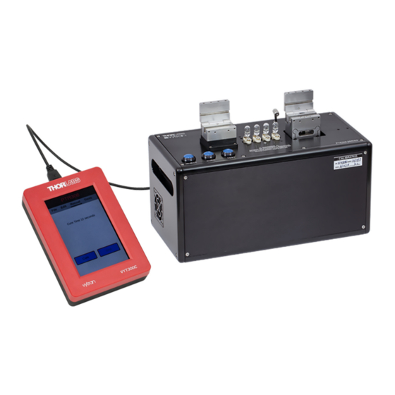
Chapter 3 Description The PTR306 and PTR306B are combination optical fiber Recoater and Linear Proof Testers. The recoat mold applies a flexible UV acrylate coating to a fusion spliced section of fiber, and the proof test function ensures that a fiber or fusion splice meets a minimum strength requirement. - Page 8 PTR306 / PTR306B Recoaters with Linear Proof Testers Chapter 3: Description Figure 1 System Components Rev D, October 2, 2020 Page 5...
-
Page 9: Chapter 4 Device Selection
Inserts for Fiber Holding Blocks When purchasing a PTR306 or PTR306B, the proper set of inserts need to be selected. A total of four inserts (two top and two bottom) are required for a full unit. The inserts are seated in and secured to the fiber holding blocks. -
Page 10: Chapter 5 Setting Up The Unit
Removing the shipping fixture Loosen the set screws in the fiber holding blocks using the hex key. Open the lids and lift out the shipping fixture. Save the shipping fixture in case you ever have to ship the PTR306/PTR306B anywhere. Figure 2... - Page 11 PTR306 / PTR306B Recoaters with Linear Proof Testers Chapter 5: Setting up the Unit Figure 4 Attach the Recoat Mold Assembly Lower the assembly straight down over the recoat lamps and attach the recoat mold assembly using the five flange screws from the attached bag.
- Page 12 PTR306 / PTR306B Recoaters with Linear Proof Testers Chapter 5: Setting up the Unit Connecting the Wires Plug in the AC power cord. The power supply accepts an AC input of 100 - 240 VAC; 47 - 63 Hz. Connect the AC power cord to the external power supply.
- Page 13 PTR306 / PTR306B Recoaters with Linear Proof Testers Chapter 5: Setting up the Unit Plug this USB plug into the top USB socket of the handset. Note that the USB socket on the side of the handset is dedicated to...
-
Page 14: Chapter 6 Controlling The Ptr306/Ptr306B
The PTR306 and PTR306B have three Unit Control Buttons that enable the user to inject and cure recoat material as well as test the strength of a fusion splice. The inject button is only enabled on the PTR306, which comes with the automatic injection system. -
Page 15: Ptr306 And Ptr306B Parameters
PTR306 / PTR306B Recoaters with Linear Proof Testers Chapter 6: Controlling the PTR306/PTR306B Controller will auto-detect the PTR306 or PTR306B and display the main screen. From here the User can start injecting, curing, testing, and manipulating system parameters. Chapter 7 contains a detailed view of the features and capabilities of the Handset Controller. -
Page 16: Advanced Parameters
Advanced parameters are accessed from the toolbar since they are rarely modified. Shrink Factor: For Auto Inject, PTR306 only. The Shrink Factor is the amount of material injected into the recoat mold during the early stages of curing. This is entered as a percentage of the initial Inject volume and is intended to compensate for material shrinkage during cure. - Page 17 Chapter 6: Controlling the PTR306/PTR306B Priming the Injection System Both the PTR306 and PTR306B can be injected manually if necessary. The PTR306B comes standard with the remote manual injector, whereas the PTR306 comes standard with the automatic injector. For priming the injection system go to the appropriate section below.
- Page 18 PTR306 / PTR306B Recoaters with Linear Proof Testers Chapter 6: Controlling the PTR306/PTR306B Remote Manual Injection System (PTR306B) The PTR306B includes the remote manual recoat injector which is fitted to the right side of the unit. This option provides a method of manually dispensing recoat material directly from the recoat bottle into the injection port. This system consists of a syringe with a knurled dispensing screw, which is fitted to a distribution valve with a two- position selection lever.
- Page 19 Automatic Injection System (PTR306) The PTR306 comes with the automatic recoat injection pump fitted inside the unit. It is very important to remove all air from this recoat injection system prior to performing a recoat. When operating the system for the first time, the pump must be filled with recoat material and cleared of all air in the pump and tubing.
-
Page 20: Recoat Process
PTR306 / PTR306B Recoaters with Linear Proof Testers Chapter 6: Controlling the PTR306/PTR306B Five (5) Purge cycles are required to fill the pump with recoat material and force any air out of the pump system. This will take approximately 15 minutes to complete. - Page 21 2. Make sure both quartz plates are clean and that the injection port has enough UV material for the recoat (Manual Injection) or that the injection system is purged (PTR306/PTR306B). 3. Hold the section of fiber to be recoated straight between two hands, making sure not to touch the exposed section of fiber (a total separation of approximately 8 inches is a convenient distance).
- Page 22 PTR306 / PTR306B Recoaters with Linear Proof Testers Chapter 6: Controlling the PTR306/PTR306B Recoating (PTR306B) Make sure that the selection lever is in the inject position (lever up). Once the fiber has been captured in the recoat mold assembly, the injection syringe should be screwed in (turned clockwise) to inject the UV acrylate material into the mold cavity.
- Page 23 PTR306 / PTR306B Recoaters with Linear Proof Testers Chapter 6: Controlling the PTR306/PTR306B Curing the Coating The liquid UV acrylate material cures to a solid state when exposed to ultra-violet light. The necessary UV radiation is provided by four tungsten-halogen lamps located below the bottom mold plate. The optical coating on the bottom plate ensures that any material which flows between the two plates will not cure and form a flashing on the recoated section of the fiber.
-
Page 24: Proof Test Process
Figure 16. The peak value reached during a proof test should be identical to the preset “Peak Tension” value, if the fiber doesn’t fail. Configure the PTR306 or PTR306B to proof test to the desired level using the handset controller’s “Edit” menu. WARNING Always wear safety glasses when proof or tension testing fiber. -
Page 25: Chapter 7 Vyt300C Handset Controller
PTR306 / PTR306B Recoaters with Linear Proof Testers Chapter 7: VYT300C Handset Controller Chapter 7 VYT300C Handset Controller The PTR306/PTR306B Manual Inject Recoater is operated using the VYT300C Handset Controller. 7.1. Power Up With the Handset Controller properly connected to the unit, turn on the PTR306/PTR306B using the switch located at the back of the unit. -
Page 26: Edit
Recoat & Test For the PTR306, when the Inject button is pressed either on the machine or on the Handset, the Handset recoat screen will show the status of the Inject process. The Stop button can be used to abort the inject process. -
Page 27: Tools
The system should be purged whenever a new bottle of material is installed. Fill (PTR306 Only): Allows the user to perform a fill operation. If an Inject sequence is initiated and the pump syringe has insufficient material to perform the inject operation, the machine will automatically fill the syringe from the material bottle. - Page 28 PTR306 / PTR306B Recoaters with Linear Proof Testers Chapter 7: VYT300C Handset Controller Terminal: The Terminal Screen provides a box where a command can be entered for transmission. Below that is a list of the most recent commands sent. Touch a command in the list to select it for re-transmission. The received communications traffic is also shown.
-
Page 29: Chapter 8 Maintenance
PTR306 / PTR306B Recoaters with Linear Proof Testers Chapter 8: Maintenance Chapter 8 Maintenance The purpose of the maintenance section is to define the planned maintenance requirements of the PTR306 and PTR306B. Where appropriate maintenance procedures are included. 8.1. Planned Maintenance The device is designed for a production environment to give trouble free operation provided normal planned maintenance is adhered to. -
Page 30: Recoat System Maintenance
Check Recoat Bulb The PTR306/PTR306B uses tungsten halogen lamps as the UV source for curing the recoat material. These lamps have a useful lifetime of 500 minutes (30,000 seconds) and degrade linearly to 50% of their initial output over this period. - Page 31 PTR306 / PTR306B Recoaters with Linear Proof Testers Chapter 8: Maintenance 11. Remove the bottle containing the solvent and dispose of the solvent according to proper handling guidelines. 12. Repeat step 5-7 with no bottle present to purge any solvent from the injection system.
- Page 32 PTR306 / PTR306B Recoaters with Linear Proof Testers Chapter 8: Maintenance Replace Recoat Material Recoat material has a finite shelf life and should be replaced every 6 months. To replace the recoat material first flush the system as outlined above. Once the system is flushed, fill a clean recoat bottle ¾ full with fresh recoat material and follow the procedures in chapter 0.
-
Page 33: Fuse Replacement
If the Proof Tester is applying a load less than expected, the proof tested section of the fiber may be weaker than required and could fail at a later time. Checking and re-calibrating the Proof Tester requires special equipment and training. Contact Thorlabs to learn more about calibration options. -
Page 34: Chapter 9 Troubleshooting
PTR306 / PTR306B Recoaters with Linear Proof Testers Chapter 9: Troubleshooting Chapter 9 Troubleshooting 9.1. Recoat Diagnostics Problem Possible Cause Solution Fiber not loaded properly. See Section 6.5: Loading the Fiber Refer to Section 8.3: Replace and Recoat mold not properly aligned... -
Page 35: Proof Test Diagnostics
PTR306 / PTR306B Recoaters with Linear Proof Testers Chapter 9: Troubleshooting 9.2. Proof Test Diagnostics Problem Possible Cause Solution Peak proof test value Clean fiber holding block inserts as does not reach preset Fiber slipped in fiber holding block described in Section 8.2: Check/Clean FHB value. -
Page 36: Chapter 10 Appendix
PTR306 / PTR306B Recoaters with Linear Proof Testers Chapter 10: Appendix Chapter 10 Appendix 10.1. Process Parameters Table 1 gives the approximate injection quantity in micro liters for different length recoats and different mold sizes. A 125 μm fiber diameter is assumed for all mold sizes except 160 μm, which is calculated based on an 80μm fiber diameter. -
Page 37: Material Data Safety Sheet
PTR306 / PTR306B Recoaters with Linear Proof Testers Chapter 10: Appendix 10.2. Material Data Safety Sheet Page 34 TTN090913-D02... - Page 38 PTR306 / PTR306B Recoaters with Linear Proof Testers Chapter 10: Appendix Rev D, October 2, 2020 Page 35...
- Page 39 PTR306 / PTR306B Recoaters with Linear Proof Testers Chapter 10: Appendix Page 36 TTN090913-D02...
- Page 40 PTR306 / PTR306B Recoaters with Linear Proof Testers Chapter 10: Appendix Rev D, October 2, 2020 Page 37...
- Page 41 PTR306 / PTR306B Recoaters with Linear Proof Testers Chapter 10: Appendix Page 38 TTN090913-D02...
- Page 42 PTR306 / PTR306B Recoaters with Linear Proof Testers Chapter 10: Appendix Rev D, October 2, 2020 Page 39...
- Page 43 PTR306 / PTR306B Recoaters with Linear Proof Testers Chapter 10: Appendix Page 40 TTN090913-D02...
- Page 44 PTR306 / PTR306B Recoaters with Linear Proof Testers Chapter 10: Appendix Rev D, October 2, 2020 Page 41...
-
Page 45: Chapter 11 Declaration Of Conformity
PTR306 / PTR306B Recoaters with Linear Proof Testers Chapter 11: Declaration of Conformity Chapter 11 Declaration of Conformity Page 42 TTN090913-D02... - Page 46 Waste Treatment is Your Own Responsibility If you do not return an “end of life” unit to Thorlabs, you must hand it to a company specialized in waste recovery. Do not dispose of the unit in a litter bin or at a public waste disposal site.
- Page 47 PTR306 / PTR306B Recoaters with Linear Proof Testers Chapter 13: Thorlabs Worldwide Contacts Chapter 13 Thorlabs Worldwide Contacts For technical support or sales inquiries, please visit us at www.thorlabs.com/contact for our most up-to-date contact information. USA, Canada, and South America UK and Ireland Thorlabs, Inc.
- Page 48 www.thorlabs.com...
Need help?
Do you have a question about the PTR306 and is the answer not in the manual?
Questions and answers