Advertisement
Quick Links
Please read the installation
instructions carefully before
using your PSC. Make sure
you fully understand and
agree
with
disclaimer
before using this product.
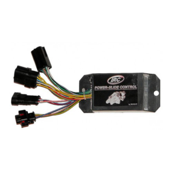
POWER SLIDE CONTROL
The Power Slide Control is our latest high performance creation; we put down an
enormous amount of time and engineering into it, to create an effective and reliable
product. It is developed by racers for racers.
The Power Slide Control is an electronic system able to reduce the rear wheel slide off
during accelerations and constant throttle. It is not able to reduce the slide off during the
braking phase.
The system is composed by an ECU and 2 velocity sensors put on front and rear wheels.
The variation of the difference between front and rear wheel velocities is continuously
monitored in order to understand if the rear wheel is sliding off or not. The Power Slide
Control is able to understand if the bike is on straight, or in a slow turn or in a fast turn, and
consequently acts.
PRESENTS
1 di 18
Advertisement

Subscribe to Our Youtube Channel
Related Manuals for IRC POWER SLIDE CONTROL

Summary of Contents for IRC POWER SLIDE CONTROL
- Page 1 It is developed by racers for racers. The Power Slide Control is an electronic system able to reduce the rear wheel slide off during accelerations and constant throttle. It is not able to reduce the slide off during the braking phase.
- Page 2 DISCLAIMER The Power Slide Control is intended for use on a closed circuit only. The Power Slide Control is not road homologated. The Power Slide Control is not a safety component. Sliding losses mean possible driver crash; the Power Slide Control aim is only to support the driver in this phase, reducing or deleting, if possible, the sliding conditions.
- Page 3 WARNING : Although the PSC ECU are all identical, the software could be different in function of application (engine type or connection type – injectors or ignition). Each single ECU has a label indicating the diagnosis and cut software version. Check on the website if it is matching with your engine and installation type.
- Page 4 WARNING : Sensors’ brackets must stiff, welll fastened and not bending. Take care on rear sensor’s bracket: during the chain adjustment operation, the rear sensor must be aligned with his target. A disaligment could cause a wrong signal read, with impact on PSC system operation. 2.
- Page 5 “real” positive the highest voltage one. Refer to the following proper paragraph 3.1.1. JAPANESES SPORTS BIKE (Coils on spark plugs) & TRIUMPH Unplug coils and determine the positive wire. If, at the order you specify the bike, the harness will be supplied with end line connectors already plugged;...
- Page 6 To connect the harness-connectors act as described: Insert male pins on the small connector. Close it with the yellow plastic key. Insert female pins on the big connector. Close it with the yellow plastic key. 3.1.2. Engines with coils not integrated on plug sparks: 6 di 18...
- Page 7 Locate the coils and how many they are. Use the proper number of PSC connectors following this order: green/black-grey, green/red-orange. Cut off the PSC plug & play connectors. Unplug the connectors of the coils; locate pulse wires (usually they are different colour for each coil), cut it.
- Page 8 MV and RSV4: , take another coil harness. Unplug the connectors of the coils; locate pulse wire (usually they are different colour for each coil), cut it. Connect the ECU side with the green/red wire and the orange wire to the coil wire. Seal off the not used wires.
- Page 9 Use the proper number of PSC connectors following this order: green/black-grey, green/red-orange. Cut off the PSC plug & play connectors. Unplug the connectors of the injectors; locate pulse wire (usually they are different colour for each coil), cut it. Connect the ECU side with the green/black wire and the grey wire to the injector wire.
- Page 10 WARNING : Take care to the arrow direction! First of all set up the number of “pulses” for both front and rear sensors, acting on the left selector switch according to the following table: FRONT REAR SETTING FRONT REAR SETTING Then measure the circumferences of front ad rear wheels, in the center of the tyre, and make the difference between the 2 values.
-
Page 11: Dashboard Installation
WARNING : A too high ratio set could cause PSC acting even in the straigth and in the acceleration phase. 5. DASHBOARD INSTALLATION Install the potentiometer, the 2 switches and the 2 leds, in the carbon plate included in the kit. - Page 12 WARNING : Put the dashboard taking care that the 2 leds are oriented directly towards the driver’s eyes. Sensitivity potentiometer is positioned in order to have the system OFF if counter clockwise rotated and maximum sensitivity if completely rotated clockwise, according to numbers in the sticker.
-
Page 13: Pre Use Checks
It allows to reconnect the coils as per OEM application, completely disconnecting system. It’s ON or OFF according to pictures on the right. Suggestion for the switch positioning: System ON towards down (ie. The front wheel must be down) and System OFF upward. - Page 14 Test the bike in straight with dirty ground. The PSC will cut power at the minimum traction loss. Switch the Launch Control ON. Test the system, with the highest possible gear that allows the front wheel rise due to power and not in first gear. The PSC will work carrying the front wheel again on the ground.
-
Page 15: Troubleshooting
Check harness connections on first 2 flashes Error on first cylinder cut. cylinder (Green/black-Grey wires). Follow procedure to above 7.1. Check harness connections 4 flashes Error on second cylinder cut. second cylinder (Green/red-Orange wires). Follow procedure to above 7.1. Check all harness and conenctions 6 flashes Errore on anti spin hardware. - Page 16 running not constant power due to a traction loss loss, reduce “Sensitivity” flash condition. eventually, check “Ratio” and “Pulse”. Activate system Constant Motorcycle selecting “Sensitivity” blinking flash, The system is OFF. running different from “0” moving like arrow. the knob clockwise. 7.2 Greeen light is flashing but PSC doesn’t cut.
- Page 17 7.3 Sensors check To check that sensors read in proper manner, disconnect the sensor and connect the proper tool to be ordered apart. Switch on the PSC and SLOWLY rotate the wheel. Led must flash whenever the sensor read the target surface. If the check sensor’s kit is not available, take an amperohmeter set on 20v.
-
Page 18: Other Troubleshooting
8. OTHER TROUBLESHOOTING 8.1 system acts whenever 10Km/h are reached. System properly works but or rear sensors reading double check, or the front sensor is not reading all pulses. Check sensors’ positioning. 9. TELEMETRY SYSTEMS Connect brown/white wire to the data acquisition system. In case it is not used, seal it off. 18 di 18...
Need help?
Do you have a question about the POWER SLIDE CONTROL and is the answer not in the manual?
Questions and answers