Advertisement
Table of Contents
- 1 Table of Contents
- 2 Features
- 3 General Introduction | Warnings | Cautions
- 4 Overview
- 5 Joystick Set up
- 6 Manual Control
- 7 Scene Operation
- 8 Chase Operation
- 9 Bank Copy and Fixture Copy | Fade Time
- 10 MIDI Channel Setting
- 11 MIDI Control
- 12 DMX Addressing
- 13 Warranty
- 14 Specifications
- Download this manual
Advertisement
Table of Contents

Subscribe to Our Youtube Channel
Related Manuals for ADJ DMX OPERATOR 384


Summary of Contents for ADJ DMX OPERATOR 384
- Page 1 DMX OPERATOR 384 User Manual...
- Page 2 Products, LLC brands and product names are trademarks or registered trademarks of their respective companies. ADJ Products, LLC and all affiliated companies hereby disclaim any and all liabilities for property, equipment, building, and electrical damages, injuries to any persons, and direct or indirect economic...
-
Page 3: Table Of Contents
TABLE OF CONTENTS Features General Introduction | Warnings | Cautions Overview Joystick Set Up Manual Control Scene Operation Chase Operation Bank Copy and Fixture Copy | Fade Time MIDI Channel Setting MIDI Control DMX Addressing Warranty Specifications... -
Page 4: Features
FEATURES The DMX Operator 384 is a multifunction controller that can work as an LED controller as well as a simple MIDI controller. When operating as a stage lighting controller, the device has the following main features: • 8x4 Control Channel Faders •... -
Page 5: General Introduction | Warnings | Cautions
It is a privilege for us to be chosen as your control solution. This controller is an expansion of the simple to use DMX OPERATOR 384. We have added 6 addi- tional chase memory buttons, giving the user a total of 12 to work with. A joystick is supplied for traditional X/Y control of a moving light. -
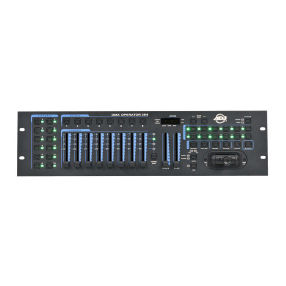
Page 6: Overview
OVERVIEW FRONT PANEL 1. Fixture buttons (1~12): Used to select relevant fixtures for control. 2. Channel faders (1~8): Used to control the output of each corresponding fixture channel. 3. Channel Bank button: Used to switch between channels 1-8, 9-16, 17~24 and 25~32. 4. - Page 7 OVERVIEW REAR PANEL 1. Label: Lists model, serial number, and production date. 2. Audio input: To connect line level input for audio trigger (0.1V-1Vp-p). 3. DB-9 connector: To connect optional external chase step controller. NOTE: No longer included in units manufactured after Feb. 2018. 4.
-
Page 8: Joystick Set Up
JOYSTICK SET UP ASSIGN JOYSTICK 1. Press and hold the Program button for approximately 2 seconds or until the PROG indicator in the LED display flashes. Once the indicator is flashing, record mode is engaged and you may release the Program button. 2. - Page 9 JOYSTICK SET UP ASSIGN JOYSTICK REVERSE (PAN/TILT INVERT) 1. Press and hold the Program button for approximately 2 seconds or until the PROG indicator in the LED display flashes. Once the indicator is flashing, record mode is engaged and you may release the Program button.
-
Page 10: Manual Control
JOYSTICK SET UP DELETE JOYSTICK PAN/TILT ASSIGNMENT 1. Press and hold the Program button for approximately 2 seconds or until the PROG indicator in the LED display flashes. Once the indicator is flashing, record mode is engaged and you may release the Program button. -
Page 11: Scene Operation
SCENE OPERATION RECORDING SCENES 1. Select the fixtures that you wish to include into your scene by pressing the FIXTURES # buttons, (1-12). The selected fixture LEDs will illuminate. 2. Press and hold the Program button for approximately 2 seconds or until the PROG indicator in the LED display flashes. - Page 12 SCENE OPERATION COPYING SCENES 1. Press and hold the Program button for approximately 2 seconds or until the PROG indicator in the LED display flashes. Once the indicator is flashing, release the Program button. 2. Select the bank that contains the scene you want to copy with the Bank UP/DOWN buttons. 3.
- Page 13 SCENE OPERATION SCENE PLAYBACK Manual Trigger 1. When powered ON, this device defaults to Manual/Blackout mode. All output will be in a black- out state until the Blackout mode is deactivated by pressing the Blackout button. To determine blackout status, check the indicator light in the display. The indicator will flash when Blackout mode is engaged.
-
Page 14: Chase Operation
CHASE OPERATION RECORDING CHASES This product has 12 programmable chases, each of which can store up to 240 scenes/steps. Please see the below instructions for chase setting. 1. Press and hold the Program button for approximately 2 seconds or until the PROG indicator in the LED display flashes. - Page 15 CHASE OPERATION ADD A CHASE STEP 1. Press and hold the Program button for approximately 2 seconds or until the PROG indicator in the LED display flashes. Once the indicator is flashing, the Program button can be released. 2. Select the Chase # button (1-12) that you wish to add a step to. The relevant Chase LED should illuminate.
- Page 16 CHASE OPERATION DELETE ALL CHASES 1. Flip the power switch OFF. The switch is located on the rear of the device. 2. Simultaneously press and hold the Auto/Del and Bank Down buttons and flip the power switch ON. All LEDs will flash three times to confirm that all chases have been deleted. CHASE PLAYBACK Manual Trigger 1.
-
Page 17: Bank Copy And Fixture Copy | Fade Time
BANK COPY AND FIXTURE COPY BANK COPY 1. Enter the Program mode. 2. Use the Bank UP/DOWN buttons to select the bank to be copied. 3. Tap the Midi/Rec button, and then use the Bank UP/DOWN buttons to select the bank you would like to copy to. -
Page 18: Midi Channel Setting
MIDI CHANNEL SETTING SET MIDI CHANNEL 1. Press and hold the Midi button for 2 seconds or until the LED-display displays “In:XX” (where “XX” represents the currently set midi channel). 2. Use UP/DOWN BANK buttons to set your desired Midi channel from 01 to 16. 3. -
Page 19: Midi Control
MIDI CONTROL By using fixture 1-13, Scene 1-13, Chase 1-13, and Fade Time Slider, the DMX Operator 384 can function as a simple MIDI controller. The MIDI control function are as follows: FOR SOFTWARE REVISIONS PRIOR TO V2.5: PAGE CHASE 1-12... -
Page 20: Dmx Addressing
DMX ADDRESSING FIXTURE NUMBER DMX FIXTURE ADDRESS... -
Page 21: Warranty
WARRANTY MANUFACTURER’S LIMITED WARRANTY A. ADJ Products, LLC hereby warrants, to the original purchaser, ADJ Products, LLC products to be free of manufacturing defects in material and workmanship for a prescribed period from the date of purchase (see specific warranty period on reverse). This warranty shall be valid only if the product is purchased within the United States of America, including possessions and territories. -
Page 22: Specifications
DB-9 connector (no longer included in units made after Feb. 2018) Ext Step Control: Dimensions: 483x135x82mm Weight: 2.2 kg (approx.) ADJ Products, LLC 6122 S. Eastern Ave. Los Angeles, CA 90040 USA Tel: 323-582-2650 / Fax: 323-582-2941 www.adj.com / info@adj.com A.D.J. Supply Europe B.V. Junostraat 2...
Need help?
Do you have a question about the DMX OPERATOR 384 and is the answer not in the manual?
Questions and answers
We had a power outage, not a surge, now lights will not come on via DMX OPERATOR 384. All power has not been affected since power restoration
The ADJ DMX Operator 384 defaults to Manual/Blackout mode when powered on. This means all output remains in a blackout state until the Blackout button is deselected. To restore manual control and turn on the lights, the user must disengage blackout by pressing the Blackout button.
This answer is automatically generated