Table of Contents
Advertisement
Quick Links
Advertisement
Table of Contents

Related Manuals for sewerin COMBIPHON

Summary of Contents for sewerin COMBIPHON
- Page 1 EDENBROS, LLC Operating Instructions...
- Page 2 Measurable success by Sewerin equipment Congratulations. You have chosen a quality instrument manufactured by Hermann Sewerin GmbH. Our equipment will provide you with the highest standards of perfor- mance, safety and efficiency. They correspond with the national and international guide-lines.
- Page 3 Operating Instructions COMBIPHON® 11.10.2010 – V 1.X – 103411 – en...
- Page 4 Hermann Sewerin GmbH accepts no liability for damage resulting from non-compliance with the foregoing. The guarantee and liability provisions in the Hermann Sewerin GmbH terms of sale and supply are not extended by the foregoing. We reserve the right to make changes in the context of continued techni- cal development.
-
Page 5: Table Of Contents
Contents Page System overview ..............1 Intended usage and principle of operation ......3 COMBIPHON system ..............5 Generator G5 ................6 Loading the Battery ..............7 Generator G5 – Radio ...............7 AC/DC adapter L ...............8 Car cable L ................9 Knocker ..................10 Knocker – Starting and operating ........... 11 Working with the Knocker............ - Page 6 Contents Page Appendix ................23 EC-Declaration of conformity ..........23 Advice on disposal ..............23 Modification History - Software ..........24 Index ..................25...
-
Page 7: System Overview
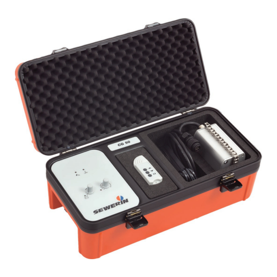
2 AC/DC adapter L 3 Car cable L 4 Knocker 5 Remote control 6 Generator G5 with control panel 7 Connection for an external power source 8 Connection for oscillator Picture 1: COMBIPHON system 9 Stopper 10 Standpipe Picture 2: Stopper and accessories... - Page 8 Generators G5 control panel Knocker LED Stopper LED Booster LED ON/OFF switch / Intensity adjuster* Battery LED Frequency LED Frequency adjuster (Knocker/Stopper) COMBIPHON Picture 3: Control panel * Intensity adjuster for Knocker only. The intensity of the Stopper is set via a valve.
-
Page 9: Intended Usage And Principle Of Operation
This is how fibre cement and metal pipes are principally detected. The COMBIPHON system consists of the Generator G5 central control unit, the AC/DC adapter L, a car cable L as well as vari- ous oscillators (Knocker, Stopper). - Page 10 2 Intended usage and principle of operation The Stopper creates a pressure wave by rapidly opening and clos- ing the flow to the pipe. Main pipes (water) require more energy to be placed under oscillation. The water column is set in motion by extracting water from a hydrant.
-
Page 11: Combiphon System
3 COMBIPHON system COMBIPHON system The following describes the various system components as well as their intended usage. The described system elements are laid out in the carrying case so that they can be easily removed for use and stowed away as well as operated from the case itself. -
Page 12: Generator G5
3 COMBIPHON system Generator G5 The Generator G5 is located on the left of the carrying case. It is an integral part of the carrying case and cannot be removed. The control elements of the generator are used to set the frequency (see Picture 3) and the intensity of the impulse used for detec- tion. -
Page 13: Loading The Battery
3 COMBIPHON system Loading the Battery Note: To maintain the device in continuous operation, it should always be connected to an external power source (e.g., via the car cable L). Detailed information In buffer mode the battery is not charged, only monitored. -
Page 14: Ac/Dc Adapter L
3 COMBIPHON system The remote control allows the intensity (Knocker) to be adjusted. It is not possible to adjust the intensity beyond that defined by the position of the adjuster on the generator. Therefore, to achieve the maximum intensity at the Knocker via the remote control, the intensity adjuster must also be rotated fully clockwise. -
Page 15: Car Cable L
3 COMBIPHON system Car cable L The car cable L is located in the carrying case in the compartment to the right of the generator (see Picture 1), below the AC/DC adapter L. It is used to supply the Generator G5 via the supplied AC/DC adapter L or a car battery. -
Page 16: Knocker
4 Knocker Knocker The Knocker is located on the right-hand side of the carrying case. This device is an oscillator which places service pipes under os- cillation. For more detailed information about pipe and leakage detection, refer to the operating instructions of the receiver (e.g., AQUAPHON). -
Page 17: Knocker - Starting And Operating
4 Knocker Knocker – Starting and operating Carry out the following steps to put the Knocker into operation. Using the chain attachment, attach the Knocker to the pipe whose course is to be located. Connect the Knocker to the Generator G5. Switch on the Generator G5 using the ON/OFF switch (see Picture 3) on the generator’s control panel. -
Page 18: Maintaining The Knocker
4 Knocker Maintaining the Knocker Note: Repairs* to the device should be performed by SEWERIN Service or by a competent person. Re- habilitation* are to be carried out using only original SEWERIN spare parts. CAUTION! The connectors of the oscillator and the AC/DC adapter L are to be connected to the Generator G5 in a dry and clean state. -
Page 19: Stopper
5 Stopper Stopper The Stopper is a separate system component that is not stored in the carrying case (see Picture 2). The Stopper creates a pressure wave by rapidly opening and closing the pipe. Main pipes (water) require more energy to be placed under oscillation. -
Page 20: Stopper - Starting And Operating
Note: Comply fully with the following instructions when starting and operating the Stopper. Note that Her- mann Sewerin GmbH cannot be held liable for dam- age caused by non-compliance. Connect the standpipe with the flushing adapter to the hydrant under professional guidance. Always flush out the hydrant and the pipeline to prevent contamination and foreign particles from collecting inside the device. -
Page 21: Working With The Stopper
5 Stopper Working with the Stopper The following provides a few instructions and tips that will make your work with the Stopper easier. Detection can be significantly influenced by the following fac- tors: Ground surface Soil density Background noises When adjusting the intensity of the impulse, take the local condi- tions into consideration. -
Page 22: Maintaining The Stopper
5 Stopper Maintaining the Stopper Particles in the water can cause the plunger in the Stopper to jam. If this occurs, clean the plunger. Proceed as follows to clean the Stopper: Cleaning the Stopper plunger and cylinder: Unscrew the socket head screws on the front of the Stopper using the supplied Allen key. - Page 23 5 Stopper Cleaning the Stopper’s intensity adjustment: Unscrew the socket head screws on the front of the Stopper using the supplied Allen key. Withdraw the valve carefully. Withdraw the pusher carefully. Flush out the valve, pusher and housing thoroughly with water. Feed the pusher and valve carefully back into the housing.
-
Page 24: Important Notes On Use And Care
5 Stopper Important notes on use and care The stopper is part of the COMBIPHON system. Even under nor- mal operating conditions it is exposed to high mechanical loads and therefore subject to substantial wear and tear. The extent of... -
Page 25: Troubleshooting
6 Troubleshooting Troubleshooting General The oscillator generates no signal Possible cause Is the generator switched on? Solution Switch on the Generator G5 (turn ON/OFF switch clockwise). Possible cause Is the oscillator connected to the genera- tor? Solution Check whether the oscillator’s connection cable is connected to the generator. -
Page 26: Stopper
6 Troubleshooting Stopper No signal can be detected Possible cause The intensity set on the Stopper is prob- ably too weak. Solution Select a stronger intensity on the Stopper. The stopper does not move Possible cause The plunger in the Stopper is jammed due to particles in the water. -
Page 27: Technical Data
7 Technical data Technical data Generator G5 and G5 Radio AC/DC adapter L Built-in lead accu 12 V/7.2 Ah Optional power supply Car battery 12 V (11 V – 14.5 V) AC/DC adapter L Charging Charging time max. 9 hours Charging temperature 0 °C –... -
Page 28: Knocker
7 Technical data Knocker Max. operating time 80 hours Min. operating time 4.5 hours Control pulse Knock period 16 ms to 80 ms (power) Knock frequency 0.4 s to 1.6 s (central position = 1 s Stopper Max. operating time 11 hours Min. -
Page 29: Appendix
Allocated EWC waste code Device 16 02 13 Battery, accumulator 16 06 05 Old instruments Old instruments can be returned to Hermann Sewerin GmbH. We will arrange for the appliance to be disposed of appropriately by certified specialist contractors free of charge. -
Page 30: Modification History - Software
Appendix 8.3 Modification History - Software V 1.0 V 1.1 – Adjustment of the Knocker intensity extended – Functions for Stopper extended Note The actual software version is indicated on an adhe- sive label behind the foam insert on the Generator G5 (see Picture 5). -
Page 31: Index
Charging 21 Operation 21 Charging temperature 21 Optional power supply 21 Charging time 21 COMBIPHON system 1, 5 Connection for an external power source Remote control 1, 7 Connection for oscillator 1 Control elements of the generator 6 Control panel 6... - Page 32 Hermann Sewerin GmbH Robert-Bosch-Straße 3 · 33334 Gütersloh · Germany Telefon +49 5241 934-0 · Telefax +49 5241 934-444 www.sewerin.com · info@sewerin.com...
- Page 33 EDENBROS, LLC Products: 1. Pipe & Cable Locators 2. Metal Detectors 3. Sewer Cameras 4. Duct Rodders & Sondes 5. Leak Noise Correlators 6. Leak Listeners 7. Noise Loggers 8. Gas Detectors 9. Ground Penetrating Radar 10. Data Loggers 11. Tools 12.
Need help?
Do you have a question about the COMBIPHON and is the answer not in the manual?
Questions and answers