
Related Manuals for Edge Scout 320


Summary of Contents for Edge Scout 320
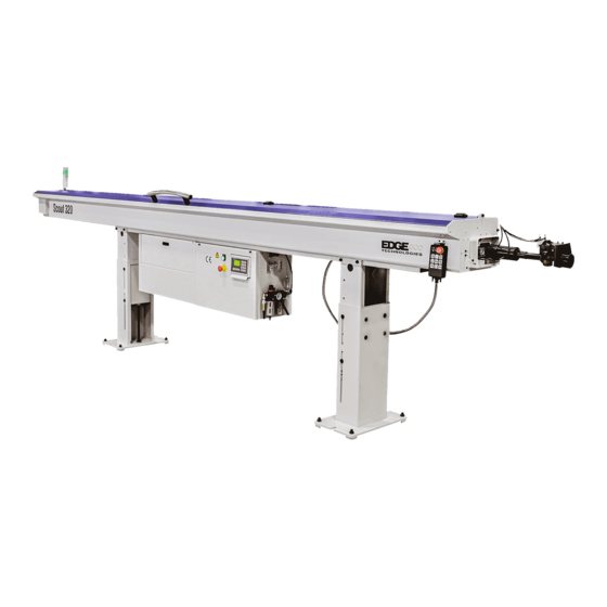
- Page 1 Scout 320 Version 3 Manual Scout 320 T h e S c o u t 3 2 0 i s a n Automatic Magazine style Bar Feeder designed for feeding round, square and hexagonal bar stock into CNC lathes.
-
Page 2: Table Of Contents
Table of Contents Section Page 1. General Information Contents of this Manual ……………………………………………………… 1 Machine Safety ………………………………………………………………. 2 Indemnification………………………………………………………………… 2 Hardware and Software Changes…………………………………………… 2 Machine Data Plate…………………………………………………………… 3 Technical Support …………………………………………………………….. 3 2. Technical Information Description of the Machine …………………………………….………..4 Machine Footprint ………………………………………………….………….. - Page 3 5. Systems and Adjustments Bar Feeder Component Locations…..………………….……………………. 28 Magazine Adjustment …….…………………………………………....29 Anti-Vibration Device/MAVD Adjustment …....…………………..30 5.3.2 AVD/MAVD Block Sets ……………………………………………………….. 33 Pusher Drive Belt ………….…………………………………………………… 34 Channel Set Components ….……………………………………..………….. 35 Material Measurement sensor/Cutting sensor ……………………………… 40 Gripper Assembly ………………………………………………………………...
- Page 4 Movable anti-vibration second closed position …………………………...… 64 First anti-vibration opening position ………………………………………….. 65 First anti-vibration closing position …………………………………………... 65 First anti-vibration second closed position ……………………………….…. 65 anti-vibration opening position …………………………………………… 66 anti-vibration opening position ……………………………………………. 66 anti-vibration opening position ……………………………………………. 67 anti-vibration opening position …………………………………………….
- Page 5 Bar feeder software version screen ………………………………………..… 83 Load original preset value screen ……………………………………………. 84 Change number for the lathe screen ………………………………………..84 Bar feeder type screen .....……………………………………………..85 Transmission ratio screen …………………………………………………….. 85 7. Maintenance Maintenance chart ……………………………………………………………... 86 7.1.2 Inspecting the pusher collet and revolving tip ………………..……………...
- Page 6 Alarm 31 ………………………………………………………………………. 95 Alarm 32 ………………………………………………………………………. 95 Alarm 33 ………………………………………………………………………. 95 Alarm 34 ………………………………………………………………………. 95 Alarm 35 ………………………………………………………………………. 95 Alarm 36 ……………………………………………………………………..95 List of Servo Driver Alarms …………………………………………………. 97 9. Electrical Parts and Schematics Electrical Parts …………….………………………………………..………… 10. Replacement Parts Replacement Parts ……………………………………………………………...
-
Page 7: General Information
Warning Indicates a potential danger to life or risk of personal injury. Exercise extreme caution. Caution Indicates a possible hazardous condition. Take precautions according to the Instructions following these warnings to help prevent injury to personnel or damage to the equipment. Scout 320 REV 3:2018... -
Page 8: Machine Safety
1.3 Indemnification User agrees to indemnify and hold harmless Edge Technologies from any and all claims or liabilities from accidents involving these machines caused by failure of users, his employees, or agents to follow instructions, warnings or recommendations furnished by Edge Technologies, or by failure of user to comply with Federal, State and local laws applicable to such equipment including the occupational Safety and Health Act of 1970. -
Page 9: Machine Data Plate
When inquiring about or ordering parts please have the machine model type and serial number on hand. Refer to the machine data plate for this information. 1.6 Technical Support For technical support please contact the Edge Technologies Service Department by phone at 314- 810-3927 or by email edgeservice@edgetechnologies.com... -
Page 10: Technical Information
12', in a diameter range of 3-27 mm, into CNC lathes. The Scout 320 comes equipped with a Mitsubishi controller and Servo drive standard. It also features dual anti-vibration devices that stabilize the bar stock at two critical points between the guide channel and lathe spindle maximizing RPM potential. -
Page 11: Machine Footprint
Lengths Measurement 4599 mm A (Max. Bar Length) 3800 mm 2150 mm 584 mm Weight 420 kg The image below references ideal spacing for operator movement. Areas of interest Scout 320 REV 3:2018... - Page 12 • D-operator area • E-supply area • F-remnant material area The space must provide adequate working area. Scout 320 REV 3:2018...
- Page 13 2.3 Machine Specifications and Capacities Oil Viscosity Brand Description Energol CS 100 Castrol Magna 100 Chevron Circulating Oil 100 ISO 100 Movixa 100 Esso Nuto 100 Mobil Vectra Oil Heavy Shell Vitrea 100 / Tellus C 100 Scout 320 REV 3:2018...
-
Page 14: Compressed Air Supply Including Oil
Air Unit Lubricating Oil – ISO VG32 Castrol Chevron Mobil Shell Energol HLP 32 Hyspin VG32 Regal R&O 32 DTE 24 or Light Tellus 32 A: Air supply fitting B: Air regulator knob C: Oil supply knob D: Lock ring Scout 320 REV 3:2018... -
Page 15: Safety
An input to the Scout for monitoring the lathe door is available. If used, this input will prevent movement of the machine when the lathe door is open. This parameter is normally set during machine installation. It is not advisable that this feature is disabled once enabled. Scout 320 REV 3:2018... -
Page 16: Emergency Stop Buttons
Contacts from the emergency stop buttons are incorporated into the interface with the lathe emergency stop circuit to enable the lathe to be manually placed into emergency stop condition from the machine control panel. The lathe emergency stop system will place the bar feeder into emergency stop as well. Scout 320 REV 3:2018... -
Page 17: Electrical Safety
2.3 Specifications and Capacities. Failure to do so may result in injury or damage to the equipment. Normally a bar feeder is ordered from Edge Technologies to be placed with a specific lathe model. The wiring interface is set in accordance with current information received to Edge Technologies. -
Page 18: Electrical Connection
The interface cable is normally pre-wired for the lathe application when shipped from Edge. The installer should verify the connection to the lathe before applying voltage to the system. If the lathe is not equipped with an interface connection for the machine plug and cables will be supplied. -
Page 19: Transportation And Handling
Lift the machine from the side opposite the magazine maintaining sufficient clearance from the forklift mast to avoid contact. Care should be taken to keep the load balanced. Do not lift the machine any higher than necessary. Scout 320 REV 3:2018... -
Page 20: Transportation And Hoisting
Hoisting with bar feeder on pallet Using suitable lifting straps positioned under the pallet near the stands. Hoisting the bar feeder in a crate Using suitable lifting straps positioned under the pallet near the stands. Scout 320 REV 3:2018... -
Page 21: Installation
Warning be sure lathe and bar feeder emergency stop is engaged when performing the manual alingment procedure. Lathe must be operational to perform the alingment and installation with the proper chucking package. Refer to the Typical Installation Guide following this section Scout 320 REV 3:2018... -
Page 22: Typical Installation Guide
Purchase Order, as the customer will most likely be in need to initiate an Insurance claim. It is important to always communicate with the Edge Technologies when the equipment sustained any kind of damage. Together we’ll evaluate the situation and formulate a feasible solution designed to overcome the current situation, hopefully even before the customer is exposed to the trouble area. - Page 23 • Tooling available for eventual test or production run. • Will the customer switch to a different chuck in the future or regularly. Once the preparation have been made perform the following installation and alignment procedures. Scout 320 REV 3:2018...
-
Page 24: Height Adjustment
(1) 2. Adjust the screw (2) up or down to achieve correct height. Adjust the bar feed height to center the channel to the lathe spindle. 3. Tighten screw (1) when alignment is completed. Scout 320 REV 3:2018... -
Page 25: Distance From Lathe
On a sliding headstock lathe the distance is 10mm behind the work holding of the guide bushing. • Distance B is from the end of the pusher at home to the end of the bar feeder channel. • The max pusher reach is maximum 1270mm Scout 320 REV 3:2018... -
Page 26: String Alignment
Move the bar feeder so that when using a ruler or centering device, check the center of the nylon string, nose adapter (C), and spindle (D). The distance of the four directions is to be within 0.15 mm. Scout 320 REV 3:2018... - Page 27 Note: As alignment is adjusted make verify distance from bar feeder to lathe does not change. Scout 320 REV 3:2018...
-
Page 28: Laser Alignment
7. Once bar feeder has been anchored down recheck alignment. Make additional adjustment to align the bar feeder. 8. Once alignment is complete remove the laser from the lathe, target from the pusher and reattach the hood switch. Scout 320 REV 3:2018... -
Page 29: Installation Accessories
The device aids in material support between the headstock and bar feeder. This is always installed unless a special condition is present that would keep the pusher from reaching the required maximum pusher travel. Contact Edge Technologies for more information. Spindle Liner: Used to reduce spindle diameter to support the pusher. - Page 30 Spacer Ring Material Inner Diameter Diameter Spacer Ring The attachment boss for the telescoping nose attaches to is adjustable for alignment purposes via jack 4 screws. The 2 upper are circled. Scout 320 REV 3:2018...
- Page 31 Once the telescoping nose is attached and aligned to the bar feeder, adjustment to the MAVD is completed by the vertical plate at point B. The ball joint tat ships with the machine may or may not be used during the installation. Example of Synch rod assembled. Scout 320 REV 3:2018...
-
Page 32: Anchoring
This includes moving the machine on the axial track if equipped and rechecking alignment. Small adjustments to the alignment can be made by the leveling jack screws on the leveling feet. Wedge style anchor 1. Jack screw 2. Height adjustment screw 3. Concrete anchor Scout 320 REV 3:2018... -
Page 33: Spindle Liner
13mm from the rear of the chuck jaws or collet. Any further and this could cause a load or remnant ejection issue Normally a spindle liner will be part of the options ordered from Edge Technologies. Additional spindle liners may be order from Edge technologies. -
Page 34: Systems And Adjustments
5. Systems and Adjustments 5.1 Bar feeder Component Locations Scout 320 REV 3:2018... -
Page 35: Magazine Adjustment
7. Tighten the lever (1) 8. Load the desired material requirement 9. Close the bar feeder hood. 10. Reset emergency stops on the lathe and bar feeder 11. Repeat above steps when changing bar diameters 1. Lever 2. Adjustment screw Scout 320 REV 3:2018... -
Page 36: Anti-Vibration Device/Mavd Adjustment
, AVD will open press the Pre-Auto Button , AVD will close. 7. Press the Manual Button to open AVD 8. Close hood and adjustment is completed 9. The MAVD may have an opening stop screw to adjust. Scout 320 REV 3:2018... - Page 37 When the lathe collet is closed the MAVD/AVD rollers/blocks will be closed if parameter is set to operate this way. Pressing the Pre-Auto button and the lathe collet closed will command the MAVD/AVD closed. Adjust as required. Scout 320 REV 3:2018...
- Page 38 We suggest removing the 4 mounting screws of the air cylinder and rotating the air cylinder body so the air valves are pointing horizontal. This will help with the final cutting of the lathe sheet metal covers. Scout 320 REV 3:2018...
-
Page 39: Avd/Mavd Block Sets
The blocks are not intended to clamp onto the material 4 Blocks will be required to outfit the Scout. A variety of sizes are available from Edge Technologies. Example of blocks installed to MAVD Blocks are optional items, contact Edge Technologies for more information. -
Page 40: Pusher Drive Belt
5. Rotate screw (2) clockwise to tighten the belt for suitable tension. 6. Tighten the locking screw (1). 7. Close the bar feeder hood 8. Reset emergency stops and test pusher operation with the hand held pendant. Scout 320 REV 3:2018... -
Page 41: Channel Set Components
The channel set on the Scout may be changed to a variety of sizes. It is important to note the material diameter to be used in the bar feeder fits in the proper channel set. Channel set components are specific to each channel set. Scout 320 REV 3:2018... - Page 42 All components with in a channel set is specific to the size of that channel set. Combining the channel; sets will not work properly but will produce poor bar feeder performance. For available guide channel sets reference this manual or contact Edge Technologies for the most up to date information.
- Page 43 If the flag is bent it should be bent back to flat or replaced. The mounting screws should be clean and medium strength thread lock be used. Note the short end is the material contact end. Scout 320 REV 3:2018...
- Page 44 Be sure the plate is engaged over the channel section. Long feed pusher flag on small diameter channels may be welded. If the flag is excessively bent and entire pusher will be required. Scout 320 REV 3:2018...
- Page 45 When the long feed pusher is reinstalled it is important the hole in the pusher flag lines up with the air cylinder shaft. If this alignment is incorrect you may risk bending the pusher flag when the pusher swings into the channel. Scout 320 REV 3:2018...
-
Page 46: Material Measurement Sensor/Cutting Sensor
This valve is air controlled by the PLC. Note if the measurement sensor is in the wrong state of position bar changes will not occur. Scout 320 REV 3:2018... -
Page 47: Gripper Assembly
This may condition may cause a servo alarm during press upon. Adjusting parameter P14 First Feed End Position Setup to fine tune the press upon and press Scout 320 REV 3:2018... -
Page 48: Material Standards And Requirements
In most cases chamfering the lathe side of the bar is required and with spindle rotation at approximately 50rpms. Material should be relatively straight and clean. A chamfer on the leading bar edge is highly recommended. While bent stock will not necessarily cause problems within the lathe spindle while turning, it may prevent loading if bar condition is such that the bar collides with the back of the lathe spindle or it binds while feeding into the spindle. -
Page 49: Procedure For Checking Bar
0.5mm TOLERANCE ZONE FOR EACH METER INCREMENT INCREMENTS 1.7mm GEOMETRIC TOLERANCE ZONE OVER TOTAL LENGTH ROTATE BAR 360° Ø1.7MM / 3800MM Ø0.070" / 12 FT Ø0.5MM / METER Ø0.020" / 36" Scout 320 REV 3:2018... -
Page 50: Bar Stock Preparation
(corners up versus flats up). Chamfers on the lathe end of the bar are not usually required, only an edge break to ensure no burrs remain to snag on the lathe collet. -
Page 51: Hmi Operation Description
• Select and hold the shift button and the button F4. • The next screen will prompt for a password input. • Selecting the F3 button will navigate back to the main load screen. Function LCD Display area Shift Function Number Enter Run light Power light Scout 320 REV 3:2018... - Page 52 Input numbers as your request from 0 ~ 9. Use the 1 button plus the shift to add the decimal point to any value. Select the button to enter the selected value into system memory. Select to delete the previously inputted data. Scout 320 REV 3:2018...
-
Page 53: Handheld Pendant
Manual Gripping in/out LDS3 Gripper in light Manual bar-pusher rise/down LDS4 Bar pusher down light Alarm light Bar end Automatic start LDS5 Automatic start light Manual loading Manual advance (Right) Manual retreat (Left) LDS2 +Z light (Left) Scout 320 REV 3:2018... -
Page 54: Basic Movement Functions
( 3 ) Resetting the Bar Feeder Home Position When guide channel up/down light is on move the pusher at least 16 inches from the home position. Press simultaneously for 3 seconds to begin resetting the bar feeder home position. Scout 320 REV 3:2018... -
Page 55: Loading And Unloading Bar Stock
The bar feed will then automatically remove the bar from the bar feed collet and continue to move the bar forward with the grippers until the bar presence sensor is clear. The bar feed will then open the channel allowing for bar removal from the guide channel Scout 320 REV 3:2018... -
Page 56: Tower Light
The status conditions below, When Red light is on, bar feeder is in emergency stop. When Green light is on, bar feeder is in machining mode. When Green light is flashing, bar feeder is in bar change operation. Scout 320 REV 3:2018... -
Page 57: Hmi Operator Functions
To access the F menus use the table below. Selecting the shift and F keys together are required for selection. Press the key: Press the key: Press the key: Press the key: Press the key: Press the key: Press the key: Press the key: Press the key: Scout 320 REV 3:2018... -
Page 58: Changing The Unit Of Measure
Warning only properly trained individuals should perform adjustment to parameters of bar feeder. The standard shipping unit of measure of the Scout 320 is metric. Imperial unit of measure can be used however this requires the reprograming of the PLC, HMI and a change to the servo drive parameter. -
Page 59: L02 Feed Too Long Safety Of Chuck Close
Alarm data chart AL.P1 Alarm data chart AL.P2 Alarm data chart AL.P3 Alarm data chart AL.P4 Interface signal monitor PLC INPUT signal monitor PLC OUTPUT signal monitor PLC Ladder PLC ERROR P. 6 – 10 TO continue Scout 320 REV 3:2018... -
Page 60: S04 First Feeding Speed
T02 Chuck close over time T03 Thrust of chuck close delay T04 Retract delay time T05 Inching signal ON time T06 Inching signal OFF time T07 Start signal delay time T08 Timer setting after chuck open to reduce torque Scout 320 REV 3:2018... - Page 61 F08 Change start signal to CNC F09 Safety door signal Of lathe F10 End of bar change mode F11 Select bar pusher work method F12 Select loading method F13 Bar feeder type F14 Bar end mode Scout 320 REV 3:2018...
- Page 62 Bar end position fine than 200 or large than 200, then adjust the parameter P11, bar end tuning position value. Movable anti-vibration Under Auto-Mode, Anti-vibration Device will close when bar early close position pusher reached this parameter setup position. Scout 320 REV 3:2018...
- Page 63 Next page (however you may add more if required) = Long feed Home page safety. Setting the value too close to the Finished Product length could cause alarms. 3.7XL Generally value: Setting range: 0~2200mm Setting value: Scout 320 REV 3:2018...
- Page 64 Next page (however you may decrease more if required) = Short Home page feed safety. Setting the value too close to the Finished Product length could cause alarms. 3.7XL Generally value: Setting range: 0~2200mm Setting value: Scout 320 REV 3:2018...
- Page 65 Input the number of required inching movement times. Home page Note: It is advised that both ends of the bar stock is chamfered to assist with loading of the bar. 3.7XL Generally value: Setting range: 0~50 times Setting value: Scout 320 REV 3:2018...
- Page 66 When a material change over from Previous page a small diameter stock to a large diameter stock or Next page vice versa this value may require adjustment for error Home page free production. 3.7XL Generally value: Setting range: 0~500rpm Setting value: Scout 320 REV 3:2018...
- Page 67 Set actual speed to avoid crashing. This is only used when a front eject collet is installed and the process Previous page requires the remnant to be ejected from the lathe Next page side. Home page 3.7XL Generally value: Setting range: 0~500mm Setting value: Scout 320 REV 3:2018...
- Page 68 Note: When setting value is too high it could cause servo Previous page failure. Setting is normally 0 since this parameter is Next page rarely used. Home page 3.7XL Generally value: Setting range: 0~800mm Setting value: Scout 320 REV 3:2018...
- Page 69 Note: Set actual speed to avoid crashing. This only changes Next page the speed from a predetermined position. The Home page position of torque change is not adjustable. 3.7XL Generally value: Setting range: 0~800mm Setting value: Scout 320 REV 3:2018...
- Page 70 Setting method: Add 150mm to the MAVD opening position. Note: To disable this parameter function, set the value to Previous page zero. Next page Home page 3.7XL Generally value: Setting range: 0~5000mm Setting value: Scout 320 REV 3:2018...
- Page 71 "First anti-vibration opening position." Setting method: Input the required length. Previous page Note: To disable this parameter function, set the value to zero. Next page Home page 3.7XL Generally value: Setting range: 0~5000mm Setting value: Scout 320 REV 3:2018...
- Page 72 Note: The Third anti–vibration should be opened before the Home page end of the push bar will be arrived to avoid the material was separated from the collet. 3.7XL Generally value: Setting range: 0~5000mm Setting value: Scout 320 REV 3:2018...
- Page 73 Note: The Five anti–vibrations should be opened before the Home page end of the push bar will be arrived to avoid the material was separated from the collet. 3.7XL Generally value: Setting range: 0~5000mm Setting value: Scout 320 REV 3:2018...
- Page 74 On a Swiss headstock the facing position is about Home page 10mm behind the guide bushing gripping pads. 3.7XL Generally value: Setting range: 0~4000mm Setting value: Chuck Facing Distance Setup Parameter P10 Guide Bushing Chuck Facing Distance Setup Parameter P10 Scout 320 REV 3:2018...
- Page 75 HMI and subtract 10mm from the value. Place that value into the Bar End Position. Note: Reference figure 3 3.7XL Generally value: Setting range: 0~4000mm Setting value: 5~10mm 5~10mm Chuck Pusher Pusher moved into spindle Scout 320 REV 3:2018...
- Page 76 Input position into HMI. Note: The Scout uses a moving gripper assembly, use Previous page caution when positioning for a new bar. Next page Home page 3.7XL Generally value: Setting range: 0~2000mm Setting value: Scout 320 REV 3:2018...
- Page 77 30mm and the bar pusher is within the A area, the bar Next page pusher will retract to 30mm after chuck closed. Home page Note: This parameter is only used for fixed headstock lathes. 3.7XL Generally value: Setting range: 0~300mm Setting value: Scout 320 REV 3:2018...
- Page 78 800mm and the bar pusher is out of the A area, the bar pusher will retract to 800mm after chuck closed. Note: This parameter is only used for fixed headstock lathes. 3.7XL Generally value: Setting range: 0~3000mm Setting value: Scout 320 REV 3:2018...
- Page 79 Setting method: Input the required length. Note: To disable this parameter function, set the value to Previous page zero. Next page Home page 3.7XL Generally value: Setting range: 0~2000mm Setting value: Scout 320 REV 3:2018...
- Page 80 Setting method: Input the required time. Previous page Note: Setting the time too long may cause alarms. Next page Home page 3.7XL Generally value: Setting range: 0~9.9 seconds Setting value: Scout 320 REV 3:2018...
- Page 81 Setting method: Input required time. Note: Normally not used on Swiss headstocks. Lathe must Previous page support function. Next page Home page 3.7XL Generally value: Setting range: 0~9.9 seconds Setting value: Scout 320 REV 3:2018...
- Page 82 Setting method: Input the required length. Previous page Note: To disable this parameter function, set the value to Next page zero. Home page 3.7XL Generally value: Setting range: 0~9.9 Setting value: Scout 320 REV 3:2018...
- Page 83 The new bar will be pushed to the setting chuck Previous page facing position by the parameter and the bar pusher Next page will stop right away. Home page Setting method: Input the desired function character 3.7XL Generally value: Setting range: Setting value: Scout 320 REV 3:2018...
- Page 84 Demo mode will simulate bar feeding and bar change process without the lathe inputs. set Previous page the mode for“1: Demo mode”. Next page Setting method: Input the desired function character Home page 3.7XL Generally value: Setting range: Setting value: Scout 320 REV 3:2018...
- Page 85 Previous page 1: The cycle start signal will be sent after bar Next page changed. Home page 2: Disable. Setting method: Input the desired function character 3.7XL Generally value: Setting range: Setting value: Scout 320 REV 3:2018...
- Page 86 2: Push out the remnant into the lathe by a new bar when bar end signal is sent and bar feeder will change another new bar. Setting method: Input the desired function character Previous page Next page Home page 3.7XL Generally value: Setting range: Setting value: Scout 320 REV 3:2018...
- Page 87 0: Chuck close On 1: Chuck open On Previous page Setting method: Input the desired function character Next page Home page 3.7XL Generally value: Setting range: Setting value: Scout 320 REV 3:2018...
- Page 88 Setting method: Input the desired function character Home page 3.7XL Generally value: Setting range: Setting value: Parameter description: Shift to display LOGO homepage on the HMI screen. Home page 3.7XL Generally value: Setting range: Setting value: Scout 320 REV 3:2018...
- Page 89 Previous page Home page 3.7XL Generally value: Setting range: Setting value: Parameter description: To displays the version number of PLC and HMI programs. Home page 3.7XL Generally value: Setting range: Setting value: Scout 320 REV 3:2018...
- Page 90 Setting range: Setting value: Parameter description: For recognizing the number of PLC and HMI programs to suit for lathe model. Note: Do not adjust this parameter. Contact Edge Technologies for further assistance. Home page 3.7XL Generally value: Setting range: 99999...
- Page 91 Parameter Description: To set transmission ratio of the bar feeder. 0: Sprocket mode 1: Pulley mode Note: The correct transmission mode must be correct for position data to be correct. Previous page Home page 3.7XL Generally value: Setting range: Setting value: Scout 320 REV 3:2018...
- Page 92 Check that pusher collet (B) has the correct tension. The collet should press on a bar with some pressure required. The collet should be able to retain a proper length remnant. Inspect for cracks of pieces of material missing. Replace as required. Scout 320 REV 3:2018...
- Page 93 Set the dial position based on the oil needs for the operating strategy employed for the bar feeder. The lower the number setting the less oil will be dispensed into the system. Verify pneumatic system oil type in section 2.3.2 Scout 320 REV 3:2018...
- Page 94 8 Troubleshooting Caution troubleshooting and diagnosis of the bar feeder must be carried out by a trained and qualified technician. Contact Edge Technologies if a qualified technician is unavailable. The PLC monitors various systems with in the bar feeder. When problems are detected with in this system an alarm code will be displayed on the HMI.
- Page 95 The center of the bar feeder Re-adjust the alignment spindle smoothly and the lathe isn't correct Material can't feed into the The front of the material is too Chamfering before loading chuck of the lathe smoothly rough. material. Scout 320 REV 3:2018...
- Page 96 ※Lathe is in alarm, reset condition for lathe alarm. ※Check remnant is stuck or jammed in grippers or collet. ※Remnant not removed from grippers, collet tension too high. ※Remnant too long to fall into tray. Scout 320 REV 3:2018...
- Page 97 ※Check LS08 Channel Open Switch for loose or damaged wiring. Alarm Number CURE ※Check for low air pressure. ※Check for correct sensor placement. ※Check for obstruction limiting movement. ※Check LS07 channel close switch for loose or damaged wiring. Scout 320 REV 3:2018...
- Page 98 ※Change proper length of material. ※Check the setting value of P11. ※Check the setting value of P10. ※Check the alarm No. on LCD display of servo whether it is abnormal. If yes, contact Edge Technologies for further troubleshooting assistance. Scout 320 REV 3:2018...
- Page 99 ※Check LS05 Pusher Introduction Switch and LS06 Pusher Extraction Switch for loose or damaged wiring ※Check the alarm No. on LCD display of servo whether it is abnormal. If yes, please contact Edge Technologies for troubleshooting. ※Servo has been stalled, check for obstruction.
- Page 100 ※Check air pressure supply. Alarm Number CURE ※Release emergency stop button ※Chuck open collet timeout exceeded setting. ※Check lathe program for correct process during automatic mode. Scout 320 REV 3:2018...
- Page 101 ※Check for an input or output of the bar change process that is causing the alarm. ※Check if loading bar sensor is loose or wiring condition is good. ※Check if loading motor is running or not. Scout 320 REV 3:2018...
- Page 102 Scout 320 REV 3:2018...
- Page 103 Servo driver microprocessor monitors and sets diagnostic trouble codes. The list of codes may indicate an external problem in the drive system or external component failure. It is important to trouble shoot the drive accurately to reduce down time. Contact Edge Technologies for further diagnostic assistance with drive faults.
- Page 104 ABS time-out warning AL. E6 Servo emergency stop AL. E8 Cooling FAN low rpm alarm Main circuit off warning AL. E9 AL. EA ABS SV ON warning AL. EC Over load alarm 2 AL. ED Torque word over Scout 320 REV 3:2018...
Need help?
Do you have a question about the Scout 320 and is the answer not in the manual?
Questions and answers