Table of Contents
Advertisement
Quick Links
Advertisement
Table of Contents

Subscribe to Our Youtube Channel
Related Manuals for Edge REBEL-V65E SERVO


Summary of Contents for Edge REBEL-V65E SERVO
- Page 2 SERVO SHORT BAR FEEDER Vs-65E/Vs-65LE MANUAL FOR USE AND MAINTENANCE REV:07 DATE:2011/11/08 COD:VSB20707...
-
Page 3: Table Of Contents
( ) CONTENT INDEX VSB2 CONTENT (INDEX) GENERALLY INFORMATION Contents Of Manual --------------------------------------------------------------------------- 1-1 The Label Of Manufacturer And Bar Feeder --------------------------------------------- 1-2 Support Of Technique ------------------------------------------------------------------------- 1-2 DATA OF TECHNIQUE Introduction Of The Bar Feeder ------------------------------------------------------------- 2-1 Machine Size ------------------------------------------------------------------------------------ 2-2 Description --------------------------------------------------------------------------------------- 2-2 Compressed Air Supply And Power Supply --------------------------------------------- 2-3 TRANSPORTATION... - Page 4 ( ) CONTENT INDEX VSB2 CONTENT (INDEX) ADJUSTMENT AND SETTING Structures Of The Bar Feeder ----------------------------------------------------------- 5-1 Adjustment And Selection Of The Bar Feeder -------------------------------------- 5-2 Adjustment Of Bar Stop ------------------------------------------------------------------- 5-2 Adjustment Of Bar Diameter ------------------------------------------------------------- 5-3 Selection Of Push Bar --------------------------------------------------------------------- 5-4 ----------------------------------------------------------------- 5-5 Optimizing Remnant Maintain Notice –...
- Page 5 ( ) CONTENT INDEX VSB2 CONTENT (INDEX) OPERATION AND ILLUSTRATIONS Operate Descriptiveness 6.8.1 HMI Program selection -------------------------------------------------------- 6-24 6.8.2 Parameter picture driftage ---------------------------------------------------- 6-25 6.8.3 Parameter application 6.8.3.1 Turning parameter --------------------------------------------------------- 6-27 ----------------------------------------------------- 6-31 6.8.3.2 Fixed parameter ------------------------------------------------------ 6-37 6.8.3.3 System function --------------------------------------------------- 6-41 6.8.3.4...
-
Page 6: Generally Information
1. GENERAL INFORMATION VSB2 GENERAL INFORMATION Please read the Manual carefully before operating feeder. Contents of manual The feeder manufacturer provides this manual, which is an essential part of the integrated products. Please act according to the indication of the manual in order to assure operators’ safety as well as machines’, and greatly achieve economic efficiency and the machine shall be long-lived. -
Page 7: The Label Of Manufacturer And Bar Feeder
1. GENERAL INFORMATION VSB2 The label of manufacturer and bar feeder A. Name of manufacturer B. Model(Type) C. Serial Number D. Manufacture Date Weight of Machine Pneumatic Pressure G. Rated Voltage H. Control Voltage Full Load Current Power K. Short Circuit Rating Wiring Drawing Number :... -
Page 8: Data Of Technique
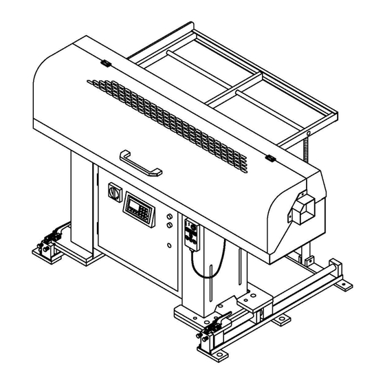
2. DATA OF TECHNIQUE VSB2 DATA OF TECHNIQUE Introduction of the bar feeder The Vs-65E/LE is designed for automatic lathes to auto feed material, the bar feeder is suitable for fixed headstock lathes. The program of the P.L.C system can control the bar feeder running with the lathe at the same time. -
Page 9: Machine Size
2. DATA OF TECHNIQUE VSB2 Machine size ALARM START OPEN M-CODE Description Vs-65E Vs-65LE Ø5mm-Ø 65mm Diameter of bar Max.1250mm Max. 1550mm Length of bar Bar length depends on Bar length depends on spindle length. spindle length. Spindle height 920mm-1300mm Weight 250kg 280kg... -
Page 10: Compressed Air Supply And Power Supply
2. DATA OF TECHNIQUE VSB2 Compressed air supply and power supply 2.4.1 Compressed air pipe minimum Ø 8mm. Minimum pressure 6 kg/cm . Compressed air consumption about 50L/H. 2.4.2 Put the air supply tube into (A). Then pull and turn around the knob (b) and set the pressure at 6kg/cm 2.4.3 Power supply 220V/380V,60/50HZ. -
Page 11: Transportation
3. TRANSPORTATION VSB2 TRANSPORTATION : Hazard-warning Transportation and hoist (please refer to the item 3.2.1 following weight table) You have to BE sure the crane; forklift or other related tools could take the weight. Using the proper equipment to move and hoist the machine should be and led by the expert personnel. -
Page 12: Transportation And Hoist
3. TRANSPORTATION VSB2 Transportation and hoist 3.2.1 Unpacking hoist Putting two steel bars (Diameter:30mm, l Length: 1M) under the bar feeder, using suitable slings which are able to bear the weight to hoist the bar feeder. Vs-65E 210KG(NET) 300KG Vs-65LE 260KG(NET) 370KG 3.2.2 On the pallet... -
Page 13: Forklift Transportation
3. TRANSPORTATION VSB2 Forklift transportation 3.3.1 Safety regulation moved by forklift 1. The operator of forklift should have been trained. 2. Select the suitable forklift. 3. Make sure the weight and the center of gravity of the machine. 4. The forks should extend under the full length of the machine body during transportation. - Page 14 3. TRANSPORTATION VSB2 (2) On board transportation (3) Wooden transportation Machine weight approx:Vs-65E -------- 300kg (660lbs) Vs-65LE ------- 370kg (814lbs) Moved by crane B. Moved by forklift...
-
Page 15: Installation Area
3. TRANSPORTATION VSB2 Installation area In order to fix the feeder securely, the floor must be flat and firm. According to the operation of the bar feeder, planning a suitable area in advance. Area:(D-operator area),(E-supply area),The space must be enough to avoid the feeder caused crashed by the operator. -
Page 16: Installation
INSTALLATION VSB2 INSTALLATION Bar feeder-Installation Before installing the bar feeder, the spindle of the lathe must be horizontal and the Lathe is fixed on the ground strongly. Height adjustment 4.2.1 Disengage the screw (1). 4.2.2 Adjust the screw(2)and shift from up to down. Adjust the height to a straight line between the center of the bar feeder and the center of the lathe. -
Page 17: Initial Position
INSTALLATION VSB2 Initial position 4.3.1 Distance between Vs-65E/LE and CNC-lathe In order to use the automatic bar feeder in the best possible way you should see to it that the distance between the CNC-lathe and the bar feeder is not too short!! You may;... -
Page 18: Directional Adjusting
INSTALLATION VSB2 Directional adjusting ! IMPORTANT! During directional adjusting the push bar must not touch the lathe spindle!! The height must have been adjusted roughly beforehand and has to be readjusted if necessary. The direction has to be adjusted rather exactly as the adjusting range for precision adjusting is limited. -
Page 19: Mounting Of The Feeder Frame
INSTALLATION VSB2 Mounting of the feeder frame 4.5.1 First, put the lever into support tube ( 1 ) 4.5.2 The support profile fixed with the extension ( 2 ) and fastened in the suitable height with screw ( 3 ) 4.5.3 Then the middle support profile fixed with the extension ( 4 ) 4.5.4... -
Page 20: Accessories Installation
INSTALLATION VSB2 Accessories installation 4.7.1 Axial displacement (optional) 4.7.1.1 Place two woods (height: about 10cm) under the bar feeder. 4.7.1.2 Place axial displacement by each side under stands of the bar feeder (axial displacement has two parts: right part and left part) 4.7.1.3 Push the stands to the end of axial displacement and fix. - Page 21 INSTALLATION VSB2 4.7.4 Spindle liners 4.7.4.1 How to select correct spindle liners: The inner diameter of the spindle has to be adjusted to the outer diameter of the bar stock. According to our experience, the diameter of spindle of blank bar stock should be bigger by 3mm to 5mm than the diameter of bar stock.
-
Page 22: Adjustment And Setting
5. ADJUSTMENTS AND SETTING VSB2 ADJUSTMENTS AND SETTING Structure of the bar feeder... -
Page 23: Adjustment And Selection Of The Bar Feeder
5. ADJUSTMENTS AND SETTING VSB2 Adjustment and selection of the bar feeder 5.2.1 Adjustment of lever system 5.2.1.1 The inclination of the feeding frame − depends on the kind of bar stock used: round bar stock:α about 5° ~ 8° hexagonal bar stock:α... -
Page 24: Adjustment Of Bar Diameter
5. ADJUSTMENTS AND SETTING VSB2 Adjustment of bar diameter 5.4.1 Turn to the manual position , and press until it is lighted. 5.4.2 Swing the handle (2) to adjust the graduation as same as the diameter of bar on a graduated meter (3). -
Page 25: Selection Of Push Bar
5. ADJUSTMENTS AND SETTING VSB2 Selection of push bar: The push bar has to be adjusted to the bar diameter: push bar bar stock Ø6mm to Ø15mm Ø12mm Ø15-25mm Ø20mm from Ø25mm Changing of push bar: ※ Pull the PIN 1 out ※... -
Page 26: Optimizing Remnant
5. ADJUSTMENTS AND SETTING VSB2 Optimizing remnant By observing the following items the remnant length will be reduced to a minimum: 5.6.1 ※ Exact adjustment of bar end .(refer to 6.3.1) 5.6.2 ※ Machining and cutting off very close to chuck . 5.6.3 ※... -
Page 27: Maintain Notice-Key Switch
5. ADJUSTMENTS AND SETTING VSB2 Maintain notice-key switch 5.7.1 If the safety cover is open, the bar feeder can’t use the automatic mode, but it still can be use manual mode. (1) Need to use the automatic mode when the safety cover is open. Please turn the key-switch to “OFF”. -
Page 28: Operation And Illustrations
6. OPERATIONS AND ILLUSTRATIONS VSB2 OPERATIONS AND ILLUSTRATIONS Material preparation Caution & prevention Please don’t put the material out of standard. List1-The max length of material Type Max length (mm) 1250 VS-65E 1600 Bar length depends on spindle length. 1550 Vs-65LE 1900 Bar length depends on spindle length. -
Page 29: Electricity Position
6. OPERATIONS AND ILLUSTRATIONS VSB2 Electricity Position Code Function Part No. Code Function Part No. J311701 Safety switch 10 PB1 Power ON switch J311502 Optical fiber sensor J310403 11 Remote control pendent (refer to 6.3.5) J311801 Detect back cover 12 LS5 Detect axial displacement J311802 Detect for loading... - Page 30 6. OPERATIONS AND ILLUSTRATIONS VSB2 6.2.1 Control box MERLIN GERIN multi9 Telemecanique C60a 400V¡ã 4500 23878 MELSEC 0¡DOFF 0¡DOFF 0¡DOFF Code Appellation Part No. No Code Appellation Part No. J511400 PCB1 Interface circuit board PCB3 Pulse change device J220307 J221010 PLC Programmer controller TB Ground terminal blocks J610502...
-
Page 31: Operation Box
6. OPERATIONS AND ILLUSTRATIONS VSB2 Operation box 6.3.1 Shift Function LCD Display area Shift Function Number Enter Run light Power light... - Page 32 6. OPERATIONS AND ILLUSTRATIONS VSB2 6.3.2 Monitor function description Shift–display:Press the key according to the indication on the display. (1) :Page up (2) :Page down (3) :Back main contents 6.3.3 Set up an input for numbers: (1) Input numbers as your request from 0~9. (2)...
- Page 33 6. OPERATIONS AND ILLUSTRATIONS VSB2 6.3.5 The operation of keys 6.3.5.1 The function and operation of keys Code Function Code Function Emergency stop LDS3 Clamping in light Start light Manual clamping in/out Chuck open light LDS2 +Z light(left) Alarm light -Z Key Bar end light LDS4...
- Page 34 6. OPERATIONS AND ILLUSTRATIONS VSB2 6.3.5.2 Decomposition of remote control pendant Code Name Part No. Code Name Part No. J310702 ES2 Emergency stop MPCB Pc board J510400 J460340 Paster G91120401 Bottom G91120600 G91120500 Cable J420600...
- Page 35 6. OPERATIONS AND ILLUSTRATIONS VSB2 6.3.6 Description of operation: Manual operation: Turn to the manual position ; the following 4 keys can start operating. Select Auto start-point: 1. No material in the spindle: When is lightened, it is under manual mode. At this time please press until original point of push bar to lighten, press loading a new bar to V channel.
-
Page 36: Circuit Diagram
6. OPERATIONS AND ILLUSTRATIONS VSB2 Circuit diagram... -
Page 37: Solenoid Valves Diagram
6. OPERATIONS AND ILLUSTRATIONS VSB2 6.5 Solenoid valves diagram VAL4 VAL3 VAL5 料號 Code Function Specification VAL3 Motion of primary position 4V220-08 DC24V A12120200 VAL4 Motion of moving VAL5 Motion of loading material 4V210-08 DC24V A12120100 6-10... - Page 38 6. OPERATIONS AND ILLUSTRATIONS VSB2 6.5.1 Air pressure circuit diagram 6-11...
-
Page 39: Main Circuit Diagram
6. OPERATIONS AND ILLUSTRATIONS VSB2 Main circuit diagram 6-12... - Page 40 6. OPERATIONS AND ILLUSTRATIONS VSB2 6-13...
- Page 41 6. OPERATIONS AND ILLUSTRATIONS VSB2 6.6.1 PLC input 6-14...
- Page 42 6. OPERATIONS AND ILLUSTRATIONS VSB2 6-15...
- Page 43 6. OPERATIONS AND ILLUSTRATIONS VSB2 6-16...
- Page 44 6. OPERATIONS AND ILLUSTRATIONS VSB2 6.6.2 PLC output 6-17...
- Page 45 6. OPERATIONS AND ILLUSTRATIONS VSB2 6-18...
- Page 46 6. OPERATIONS AND ILLUSTRATIONS VSB2 6-19...
- Page 47 6. OPERATIONS AND ILLUSTRATIONS VSB2 6.6.3 Server jumper circuit 6-20...
- Page 48 6. OPERATIONS AND ILLUSTRATIONS VSB2 6.6.4 Circuit in the remote control pendent 6-21...
- Page 49 6. OPERATIONS AND ILLUSTRATIONS VSB2 Interface signal circuit 6-22...
- Page 50 6. OPERATIONS AND ILLUSTRATIONS VSB2 6.7.1 Working cycle-CNC lathe 6-23...
-
Page 51: Hmi Program Selection
6. OPERATIONS AND ILLUSTRATIONS VSB2 6.8 Description of settings and parameter 6.8.1 HMI Program selection Press the key: Press the key: Press the key: Press the key: Press the key: Press the key: Press the key: Press the key: Press the key: 6-24... -
Page 52: Parameter Picture Driftage
6. OPERATIONS AND ILLUSTRATIONS VSB2 6.8.2 Parameter picture driftage 6-25... - Page 53 6. OPERATIONS AND ILLUSTRATIONS VSB2 6-26...
-
Page 54: Parameter Application
6. OPERATIONS AND ILLUSTRATIONS VSB2 6.8.3 Parameter application 6.8.3.1 Turning parameter Parameter description: This monitor can watch present working status at any time. Watch item︰ 1︰Push bar present position. 2︰Remain effective working length of material. 3︰Remain to wait for working quantities of work piece. Next page Generally value :... - Page 55 6. OPERATIONS AND ILLUSTRATIONS VSB2 Parameter description︰This parameter setting will let feed material more stable and ensure the material to be sent to request location. But if no need to use this function that you can set it to be “0"directly .
- Page 56 6. OPERATIONS AND ILLUSTRATIONS VSB2 Parameter description︰The speed of the pusher during in automatic mode when lathe chuck open. Setting method︰ According to the bar material size and torque of chuck close to adjust speed. Note︰ When setting value is too high it could cause servo failure. Previous page Next page Generally value :...
- Page 57 6. OPERATIONS AND ILLUSTRATIONS VSB2 Parameter description︰The torque of bar pusher moves forward in manual operation mode. Setting method︰ According to required torque and speed of manual operation mode to adjust torque. Previous page Next page Generally value : 40 % Setting range :...
-
Page 58: Fixed Parameter
6. OPERATIONS AND ILLUSTRATIONS VSB2 6.8.3.2 Fixed parameter/ enter password“258” Parameter description:If bar pusher position is less than setting value that pusher will retreat to setting position when chuck close. Setting method: Input the required pusher retreating distance. For example : If the value of parameter is set to 30mm and the bar pusher is within the A area, the bar pusher will retract to 30mm after chuck closed. - Page 59 6. OPERATIONS AND ILLUSTRATIONS VSB2 Parameter description︰This position is the maximum working limit. If pusher position value is bigger than bar end setting that bar feeder will offer a bar end signal to notice lathe to prepare loading new bar material Setting Mode for fixed lathe︰In the manual mode let pusher into lathe spindle untill 5~10mm before lathe chuck .
- Page 60 6. OPERATIONS AND ILLUSTRATIONS VSB2 Parameter description:Chuck facing position is the distance between cutter facing detection to cutter facing position. We can not know if the new bar material has been pushed to chuck facing position until loading a new bar material. Setting method:...
- Page 61 6. OPERATIONS AND ILLUSTRATIONS VSB2 Parameter description:This distance is the position that bar pusher pushes out the remnant into the lathe. Setting method: Push the pusher to exceed chuck position 20mm by manual operation. Then confirm the value showing in monitor and input this value.
- Page 62 6. OPERATIONS AND ILLUSTRATIONS VSB2 Parameter description︰If the pusher can not push the new bar material to chuck facing position because it is blocked or other reasons that the pusher will have inching movement. But if it exceeds setting frequency that bar feeder will Alarm17. Setting method︰...
- Page 63 6. OPERATIONS AND ILLUSTRATIONS VSB2 Parameter description︰The pre-feeding pusher will push the bar material forward until the bar material can go into collet smoothly when bar pusher is up.. Setting method: Push pre-feeding pusher to stop position and input current position .
-
Page 64: System Function
6. OPERATIONS AND ILLUSTRATIONS VSB2 6.8.3.3 System function/ enter password“258” Parameter description︰“0:Normal": Normal working. “1 & 2:One piece machining": Under working status, the bar feeder just can push one time, the bar feeder will change bar. When the chuck is open next time, the pusher bar will push the new bar in of the spindle, then next working. - Page 65 6. OPERATIONS AND ILLUSTRATIONS VSB2 Parameter description︰“0:Stop point": Under Auto working status, when the chuck is open, the pusher bar will send the material to required finish product length, at this time the cutter must be situated in outer of the spindle to wait the material. When the material has been sending to hit the cutter, bar feeder Previous page will wait the chuck to close.
- Page 66 6. OPERATIONS AND ILLUSTRATIONS VSB2 Parameter description︰“0:Circle shape": While the bar feeder had the action of inching then the bar feeder will send the signal of inching to lathe. “1:Complicated shape": While the bar feeder had the action of inching then, bat the signal of inching won't send out.
- Page 67 6. OPERATIONS AND ILLUSTRATIONS VSB2 Parameter description: To verify the version number of PLC and HMI programs. Generally value : Setting range : Home page Setting value : 6-40...
-
Page 68: Particular Function
6. OPERATIONS AND ILLUSTRATIONS VSB2 6.8.3.4 Particular function / enter password“258” Parameter description: Set two modes to normally operate, if set the mode to“0:ON-line mode", bar feeder starts operating along with lathe. If need bar feeder to cycle automatically without connective, please set the mode for“1:Demo mode". - Page 69 6. OPERATIONS AND ILLUSTRATIONS VSB2 Parameter description︰This is the bar feeder required a bar end signal to send the timing for CNC program, relative to the description of sequence, please refer to the description of sequence of movement signal in article 6.7.1. Previous page Next page Generally value :...
- Page 70 6. OPERATIONS AND ILLUSTRATIONS VSB2 Parameter description: This parameter allow technician to test each signal output on interface is continued to lathe. Setting method: To executive this parameter must be under manual mode both lathe and bar feeder or could cause danger. Generally value :...
- Page 71 6. OPERATIONS AND ILLUSTRATIONS VSB2 6.9 Refer alarm message 6.9.1 HMI Alarm Message ERROR / CAUSE CURE ※ Please check the value of long feed safety is correct ※ Check the turret whether it is at correct position of stopping material ※...
- Page 72 6. OPERATIONS AND ILLUSTRATIONS VSB2 ERROR / CAUSE CURE ※ Please refer to (6.2), LS5 is operative while SS1 is opened. ※ Please push the bar feeder to correct position of working. ※ Check the pressure of the compressed air. ※...
- Page 73 6. OPERATIONS AND ILLUSTRATIONS VSB2 ERROR / CAUSE CURE ※ Check the alarm No. on LCD display of servo whether it is abnormal. If yes, please inform the relevant technician about abnormal code to analyze reasons. ※ Check the bar feeder was in auto status when CNC is machinin normally, otherwise bar feeder can't feed material.
- Page 74 6. OPERATIONS AND ILLUSTRATIONS VSB2 6.9.2 SV List of alarm message LIST OF SERVO DRIVER ALARM Display Name AL. 10 Under voltage AL. 12 Memory error 1 AL. 13 Clock error AL. 15 Memory error 2 AL. 16 Encoder error 1 AL.
Need help?
Do you have a question about the REBEL-V65E SERVO and is the answer not in the manual?
Questions and answers