Table of Contents
Advertisement
Advertisement
Table of Contents

Related Manuals for Nidac Presco 3 Series


Summary of Contents for Nidac Presco 3 Series
- Page 1 PAC1 Single Door Access Controller “Series 3” INSTALLATION MANUAL...
-
Page 2: Table Of Contents
TABLE OF CONTENTS PAGE Introduction ..............1 Features ................1 Changes From Series 2 ..........2 Specifications ..............2 Terminal Descriptions ............ 3 Programmable Features Description ......5 Automatic Relock Function .......... 5 Door Open Too Long ........... 5 Door Forced Open ............5 One Minute Lockout ............ - Page 3 Reset All Memories Codes ........12 Basic Set Up Sequence ..........13 Automatic Relock. Memory 80 ......... 14 EGRESS Switch Type. Memory 81 ......14 ELC Relay Type. Memory 82 ........15 ELC Operating Time. Memory 83 ......15 Door Input Enable. Memory 84 ........ 15 Door Open Too Long Timer.
-
Page 4: Introduction
INTRODUCTION The Presco™ Digital Door Access Decoder utilises the latest microprocessor technology to operate most electric door locking devices on the market. The decoder together with an encoder (Presco™ keypad (PRE or PSE) or a Presco™ Interface Module (PIM) with a Clock & Data (magnetic card format) or Wiegand output reader) offers access control to restricted areas. -
Page 5: Changes From Series 2
CHANGES FROM SERIES 2 1. The PAC1 now supports 600 user codes. 2. Egress input can now be programmed as edge triggered (momentary only) so that keeping the Egress input triggered will not keep the door open permanently. 3. User code programming has been simplified (refer to the supplied User Code Programming Manual). -
Page 6: Terminal Descriptions
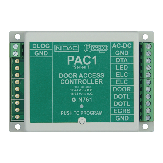
TERMINAL DESCRIPTIONS Negative input (or ground) from the power supply. AC-DC A.C. 16 - 24 Volt or D.C. 12 - 24 Volt positive input from the power supply. Data line to encoder (white wire on keypads). Output to drive a LED to indicate door unlocked. (Electric Latch Control) 5 Amp relay output. - Page 7 EGRS The EGRESS input can take either a normally open or normally closed switch between EGRESS and GND. When this input is activated the ELC relay will come on and remain on for the time that the EGRESS input is on. Once the EGRESS input is released the timing set for ELC will begin.
-
Page 8: Programmable Features Description
PROGRAMMABLE FEATURES DESCRIPTION Automatic Relock Function When the DOOR input is used then the Automatic Relock function can be used. This feature turns the ELC relay off 1 second after the door is opened (not unlocked) when a momentary code or the EGRESS input has been used (no matter how long the time for the ELC relay operation has been set for in memory 83). -
Page 9: One Minute Lockout
One Minute Lockout To increase security the PAC1 can be set to lock out all codes for a period of 1 minute after 5 incorrect codes have been tried (set in memory 87, refer to page 16). Note that this feature should not be enabled if access must be guaranteed in an emergency situation. -
Page 10: Installation
INSTALLATION Read instructions carefully before installing, programming and using the system. It is vital that all power be disconnected during wiring. To maximise security ensure that the decoder and encoder components are separated and that the decoder is inaccessible to persons outside the restricted area. The decoder should be installed indoors and in a dry secure place. -
Page 11: Pre Keypad Wiring
PRE KEYPAD WIRING PSE KEYPAD WIRING... -
Page 12: Pro2410 Proximity Reader Wiring
PRO2410 PROX READER WIRING Note that the Green, Yellow, Violet, Brown and Drain wires are not connected when the PRO2410 is used with a PAC1 decoder. * Use a 100mA inline fuse to protect the power supply from short circuiting if the PRO2410 wires are tampered with. This is particularly important when using fail safe (power to lock) locking mechanisms such as Magnetic Locks. -
Page 13: Lock
D.C. LOCK A.C. LOCK * Use 1N4004 diode only when using a Door Strike, not a Magnetic Lock or Drop Bolt. VOLTAGE FREE CONTACT OUTPUT EGRESS SWITCH INPUT DOOR SWITCH INPUT... -
Page 14: Programming
PROGRAMMING The most common method of programming is using a Presco™ keypad connected to DTA. Alternatively a PELSA1, PEL1 or PIM connected to DLOG can be used. To enable programming with a keypad the PAC1 must first be put into program mode. This is accomplished by pressing the program button located in the bottom centre of the PAC1 below the “PUSH TO PROGRAM”... -
Page 15: Using A Presco™ Keypad Without E Key
NOTE all keys in a sequence (up to and including the e) must be pressed within 10 seconds of each other. incorrect keys are pressed wait 10 seconds and then enter the sequence again. USING A PRESCO™ KEYPAD WITHOUT E KEY When using a keypad that does not have an E key (VR43, VR62 or PSE), simply use the # key instead of E at the end of the sequence, all other steps remain the same. -
Page 16: Basic Setup Sequence
BASIC SETUP SEQUENCE Enable/Disable SERIES 2 COMPATIBILITY (Currently disabled). [Memory 99, page 18] Select ELC RELAY TYPE (Currently N.O.). [Memory 82, page 15] Select EGRESS switch type (Currently N.O. level triggered). [Memory 81, page 14] Set ELC OPERATE TIME (Currently 10 seconds). [Memory 83, page 15] Enable/Disable DOOR INPUT (Currently disabled). -
Page 17: Automatic Relock. Memory 80
Automatic Relock Memory 80 (Factory Default: Enabled) Disabling the Automatic Relock function prevents the ELC relay output from deactivating 1 second after the door is opened. This function is only valid when the DOOR input is being used. To disable the Automatic Relock function… * 8 0 0 E To enable the Automatic Relock function…... -
Page 18: Elc Relay Type. Memory 82
ELC Relay Type Memory 82 (Factory Default: Normally Open) The electronic latch control (ELC) relay can be set to operate as either Normally Open (N.O.) for fail secure or Normally Closed (N.C.) for fail safe. To set the ELC relay type to normally open… * 8 2 0 E To set the ELC relay type to normally closed…... -
Page 19: Door Open Too Long Timer. Memory 85
Door Open Too Long Timer Memory 85 (Factory Default: 60 seconds) The time allowed for the door to be open before a DOTL alarm is generated can be set from 1 to 9999 seconds. A time of zero seconds will disable this function. To change the DOTL time…... -
Page 20: High Security Mode. Memory 88
High Security Mode Memory 88 (Factory Default: Normal Mode) The high security mode memory is used to select the mode that the PAC1 operates in. The value programmed into memory 88 selects either Normal Mode, Any Two User Codes, Code 000 or 001 and any other user code or Sequential Memory User Codes. -
Page 21: Momentary Codes Turn Off Toggle. Memory 91
Momentary Codes Turn Off Toggle Memory 91 (Factory Default: Disabled) When a toggle (latching) code has been used to unlock the door and keep it unlocked, a toggle code has to be used again to relock it. If this memory is enabled then any programmed user code (momentary or toggle) can be used to relock the door. -
Page 22: Installation Programming Summary
INSTALLATION PROGRAMMING SUMMARY Enable/Disable Automatic Relock. (default = enabled) * 8 0 x E. x = 0 for disabled, x = 1 for enabled. Select EGRESS switch type. (default = N.O.) * 8 1 x E. x = 0 for N.O. level, x = 1 for N.C. level, x = 2 for N.O. -
Page 23: Warranty
36 month warranty offered from the date of purchase. As NIDAC Security Pty. Ltd. or its agents do not perform the final installation, inspection or training in the use of this product, they cannot be held liable for injury, loss or damage directly or consequentially arising from the use or misuse of this product. - Page 24 Interface Module for Dallas iButton™, Clock & Data (Magnetic Card) or Wiegand readers. PAC2 2 Door Access Controller with 800 users. 100% Designed and Manufactured by: NIDAC SECURITY PTY. LTD. 2 CROMWELL STREET BURWOOD, VICTORIA Tel: (03) 9808 6244 AUSTRALIA 3125 Fax: (03) 9808 9335 www.nidac.com...
Need help?
Do you have a question about the Presco 3 Series and is the answer not in the manual?
Questions and answers