Table of Contents
Advertisement
Quick Links
PAN04
In Wall Dual relay(1 way) switch module
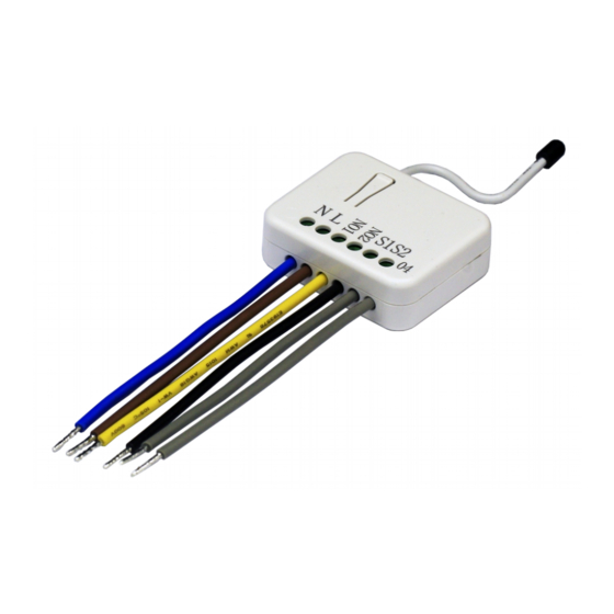
Fig 1. Assembling
This in-wall dual relay switch module is a transceiver which is a Z-Wave Plus
enabled device and is fully compatible with any Z-Wave
size design let the module can easily hide itself into the wall box and that will be
good for the house decoration.
There are many kind of application by using the module to switch AC power On
and Off, one main application is the light control. The new smart relay calibration
technology can reduce the inrush current caused by the load and let the module
work perfectly with many kind of light like incandescent, fluorescent and LED
light.
This in-wall switch module is able to detect Instant power wattage and overload
current (7.5A with resistive load) of connected light or appliances. When detect-
ing overload state, the Module will be disabled and its On/Off button will be lock-
out of which LED will flash quickly. However, disconnect and re-connect the
Module will reset its overload condition to normal status.
Adding to Z-Wave
In the front casing, there is an on/off button with LED indicator below which is
used to toggle switch on and off or carry out inclusion, exclusion, reset or
association. When first power is applied, its LED flashes on and off alternately
and repeatedly at 0.5 second intervals. It implies that it has not been assigned a
node ID and start auto inclusion.
TM
1
TM
TM
Network
enabled network. Mini
Advertisement
Table of Contents

Related Manuals for Philio PAN04


Summary of Contents for Philio PAN04
- Page 1 PAN04 enabled device and is fully compatible with any Z-Wave enabled network. Mini In Wall Dual relay(1 way) switch module size design let the module can easily hide itself into the wall box and that will be good for the house decoration.
-
Page 2: Auto Inclusion
Auto Inclusion 2. Pressing INCLUDE_BUTTON three times within 2 seconds will enter The function of auto inclusion will be executed as long as the in wall switch does inclusion mode. not have Node ID and just connect the switch to main power. Exclusion 1. -
Page 3: Choosing A Suitable Location
LED one press one flash Z-Wave device, so associations Normal Whatever we switch On and off of the PAN04 by S1 S2 or On/Off be added or removed by a controller button or RF command, the LED will lights up 1 second and then at any time. -
Page 4: Installation
PAN04 connector L, N. Configuration parameter 3=3 (default) 2. Connect the wall switch to the PAN04 as Fig1 . Report ON when either relay 1 ON or relay 2 ON 3. To manually turn ON the Switch, press and release the On/Off button. The... - Page 5 Basic Get Command: [Command Class Basic, Basic Get] [Command Class Basic, Basic Set, Value = 1~99, 255(0xFF)]: the load Basic Report Command: attached to the Switch turns on. Report OFF: [Command Class Basic, Basic Report, Value = 0(0x00)] Report ON:[Command Class Basic, Basic Report, Value = 255(0xFF)] [Command Class Basic, Basic Set, Value = 0(0x00)]: the load attached to the Switch turns off.
- Page 6 Power Consumption (Watt) of Relay2 (3) Accumulated Power Consumption 2-1-3 overload alarm report command (KWh) of Relay2 to Z-Wave Controller. When PAN04 detect the overload, it will send Alarm Report to the correspond 2-1 Auto report to Grouping 1 ~3(Maximum Node 1) Group。...
- Page 7 Meter Value 3 = 0x38(KWh) Example: Meter Value 4 = 0xA3(KWh) Meter Value 1 = 0x00 (W) Meter Value 2 = 0x00 (W) Accumulated power consumption (KW/h) = (Meter Value 2*65536) + (Meter Meter Value 3 = 0x03 (W) Value 3*256) + (Meter Value 4) = 800.35 (KW/h) Meter Value 4 = 0xEA (W) Meter(W) = Meter Value 3 *256 + Meter Value 4 = 100.2W 2-2-3 Clearing accumulated power consumption...
- Page 8 You may get the ON/OFF state from every endpoint, when endpoint set to 1, AC load current = (Meter Value 1*256) +(Meter Value 2)= 2.89 (A) PAN04 will reply state of Relay1. If endpoint set to 2, PAN04 will reply state of 2-2-6 load power factor (PF) Relay2.
- Page 9 Command Class = 0x25 (Command_Class_Switch_Binary = Relay2 ON/OFF by setting endpoint to 3 0x25) The example of the command show that switch off relay1 of PAN04 Command =0x02 (Switch_Binary_Get = 0x02) COMMAND_CLASS_MULTI_CHANNEL Below is the example show PAN04 report to last command...
- Page 10 (Bit Address+Destination End Point = 0x01) 2-3-3 METER_SUPPORTED_GET: Command Class = 0x32 (Command_Class_Meter_V3 = 0x32) This command is to ask the endpoint of PAN04 what kind of meter data can be Command =0x04 (Meter_Supported_Report = 0x04) reported Parameter 1 = 0x81...
- Page 11 (Bit Address+Destination End Point = 0x05) (Bit Address =0;Destination End Point = 2-3-5 METER_GET: command inquirer’s Endpoint value) Using meter get command to get the KWH, W, V, I, PF from endpoint of PAN04 Command Class = 0x32 (Command_Class_Meter_V3 = 0x32)
- Page 12 2-3-5-3 Get load voltage V from endpoint Parameter 1 = 0x10 (Scale = W = 0x02) Meter_GET example: COMMAND_CLASS_MULTI_CHANNEL PAN04 Instant Power Consumption (W) Report example: MULTI_CHANNEL_CMD_ENCAP COMMAND_CLASS_MULTI_CHANNEL Source End Point = 0x05 (this is the endpoint of command inquirer, here we assume endpoint is 5,if the...
- Page 13 (Scale = V = 0x04) MULTI_CHANNEL_CMD_ENCAP Source End Point = 0x05 (this is the endpoint of command inquirer, here we assume endpoint is 5,if the PAN04 AC load Voltage report example: inquirer doesn’t support multi Channel this COMMAND_CLASS_MULTI_CHANNEL value will be 0) MULTI_CHANNEL_CMD_ENCAP (Bit Address+Destination End Point = (Bit Address =0;Destination End Point...
- Page 14 Parameter 1 = 0x30 (Scale = PF = 0x06) Parameter 1 = 0xA1 (Scale Bit2 = 1, Rate Type = 0x01, Meter Type=0x01) PAN04 power factor report example: Parameter 2 = 0x4A (Precision = 2, Scale Bit1Bit0 = 0x01, COMMAND_CLASS_MULTI_CHANNEL Size = 2)
- Page 15 2. Z-Wave’s Configuration Threshold 1-10000 1KWh 10000 of KWH for Configuration Function Size Value Unit Default Description Load Parameter (Byte) Caution Watt Meter 0x01- 720*5s=3600s=1 Restore 0 : Switch off Report 0x7FFF hour switch 1 : Last switch Period state mode state 2 : Switch on 0x01-...
- Page 16 Both Relay1 and Relay2 OFF. Basic_Set or Binary_Switch_Set OFF 3-1 Watt Meter Report Period: If the setting is configured for 1hour (set value =720), the PAN04 will report its instant power consumption every 1 hour to the node of correspond Group. Get command...
- Page 17 SWITCH OFF、LAST SWITCH STATE、SWITCH ON. The state of relay1 and relay2. if the PAN04 relay change the state because of default setting is LAST SWITCH STATE.
- Page 18 3-11-2 5% : When the differential value of Watt is over 5%, PAN04 will send a PAN04 is based on 500 series SoC and supports Firmware Update Command meter report to the associated group. Class, it can receives the updated firmware image sent by controller via the Z- 3-11-3 10% : When the differential value of Watt is over 10%, PAN04 will send a wave RF media.
-
Page 19: Troubleshooting
PAN04-2: 908.40MHz; 916.00MHz(USA/Canada) The Switch not working and 1. The Switch is not 1. Check power connections PAN04-3: 922.5MHz/ 923.9MHz/ 926.3MHz (Japan) LED off connect to the Main 2. Don’t open up the Switch and send it RF Maximum Power (peak) -
Page 20: Fcc Interference Statement
(1) This device may not cause harmful interference, and purchased. They can take this product for environmental safe recycling. (2) This device must accept any interference received, including interference that may Company of License Holder:Philio Technology Corporation cause undesired operation. Address of License Holder:8F.,No.653-2,Zhongzheng Rd., Xinzhuang Dist., FCC Caution: Any changes or modifications not expressly approved by the party respon- New Taipei City 24257,Taiwan(R.O.C)
Need help?
Do you have a question about the PAN04 and is the answer not in the manual?
Questions and answers