Table of Contents
Advertisement
Quick Links
Advertisement
Table of Contents

Related Manuals for MEDIZS Smart DR13


Summary of Contents for MEDIZS Smart DR13
- Page 2 MEDIZS Inc. reserves the right to modify the product itself or specifications of the product without any prior notice, and is not required to update this documentation to reflect such changes.
-
Page 3: Table Of Contents
CONTENTS Introduction ....................6 1-1. Outline of product ......................6 1-2. Features ..........................7 Safety Information ..................8 2-1. Symbols marked on the instrument ..............8 2-2. EU Countries ........................9 2-3. Safety Instruction ......................9 2-4. General safety information ..................10 Note for using the instrument .............. - Page 4 6-5-2. Each Setting screen .................... 24 6-6. Help Guide ........................31 Operation Panel ..................33 7-1. Basic Data Operation ....................33 7-2. PD value operation ....................34 7-3. Received Data and Prescription ................35 7-4. Chart Control ....................... 39 Manual Mode Control ................40 8-1.
- Page 5 9-1-12. Far Distance Horizontal/Vertical Unequal Coincidence (Aniseikonia) ....... 57 9-1-13. Near Distance Cross Grid Test ..............58 9-1-14. Near Vision Test with Addition (Near VA with ADD) ......58 9-1-15. Near Vertical Von Graefe Test ............... 59 9-1-16. Near Horizontal Von Graefe Test..............59 10.
- Page 6 10-19. Near Point of Convergence Test ..............86 10-20. Near Point of Accommodation Test ............87 10-21. Negative Relative Accommodation Test ..........88 10-22. Positive Relative Accommodation ............... 89 10-23. Positive Relative Convergence ..............90 10-24. Near Vision with Addition ................91 10-25.
-
Page 7: Introduction
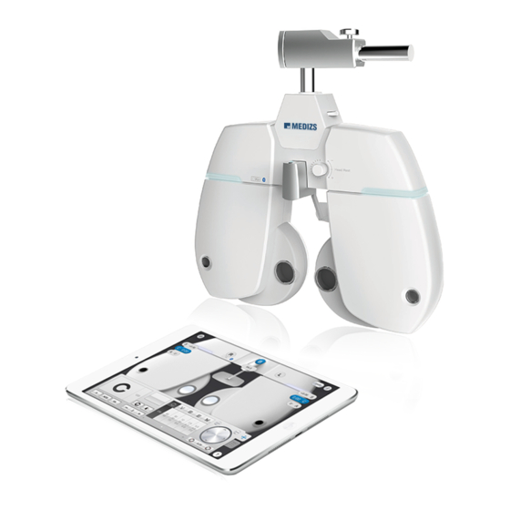
1. Introduction 1-1. Outline of product DR13, Digital Reflector of MEDIZS, is enable subjective refraction test regarding visual accommodation of patient’s eye or its function. Also, you can measure and check abnormal binocular vision such as muscle balance of the eyes, binocular balance, aniseikonia, fusion and stereo acuity. -
Page 8: Features
Measurement data tested by RK11 and LM14 can be sent to Application (Smart MEDIZS) directly, and this data can be applied on DR13 (Digital Refractor) body, only by using Tablet PC. Smart MEDIZS application allows wireless refraction test, so that allowing users ... -
Page 9: Safety Information
2. Safety Information 2-1. Symbols marked on the instrument Symbol Description Applied Part (Forehead rest) Type B Protective earth (ground) Alternating Current Direct Current Caution Manufacturer Date of Manufacture Authorized Representative in the European Community Follow Operating Instructions Power off (separated with power source) Power on (connected with power source) Do not throw away the waste to inappropriate place... -
Page 10: Eu Countries
2-2. EU Countries The following mark, the name & address of the EU Representative shows compliance of the instrument with Directive 93/42/EEC. EU Representative: CALMED INVEST Kft. 1182 Budapest, Fiume utca 3., Budapest, Hungary 2-3. Safety Instruction If you see any warnings or cautions printed on the warning labels, follow the safety instructions in this manual. -
Page 11: General Safety Information
WARING 30%~75% for normal operation. DR13 shall be connected to the separate power supply as supplied by Medizs Inc. with type DR 13J identified. WARING Do not position the equipment to make it difficult to operate the disconnection device (Appliance coupler or separable plug) WARING Grounding power cables are put in this equipment. - Page 12 In this case, just wait until condensation disappears before performing measurement. This instrument is used with accessories from MEDIZS. If consumer would like to use the accessories from other manufactures, safety of accessories should be verified and identified by manufacturer or by MEDIZS.
-
Page 13: Note For Using The Instrument
Users must operate this device strictly following user’s manual or explanations on service manual. More management is available only to service technician of MEDIZS, or who is qualified to be in proportion to that position. Be careful not to load excessive shock or vibration on this product. -
Page 14: Nominations And Functions Of Each Parts
4. Nominations and Functions of Each Parts Basic components of DR 13 are Refractor body, iPad-App and junction box. Explanation about each components and functions are following here Front side of Body 4-1. ① ② ③ ③ ④ ④ [Fig 1] Front side of Body... -
Page 15: Back Side Of Body
4-2. Back side of Body ⑤ ⑥ [Fig 2] Back side of Body Name Description ① Leveler Inform whether digital refractor maintains horizontality. ② Forehead Fixing Dial Fasten the patient’s forehead to forehead rest with dial. ③ LED Turn on when the digital refractor power ④... -
Page 16: Control Pad (Ipad-App)
4-3. Control Pad (iPad-App) [Fig. 3] Control Pad Application on iPad Buttons or Controllers are changed according to the measurement circumstance. For detailed controlling method, please refer to explanation of each mode. -
Page 17: Junction Box
4-4. Junction Box ① ② ③ Name Description ① Power switch Switch for turning power ON and OFF ② Body Connector Connect with DR13 body ③ Power Connector Power supply connector... -
Page 18: Installation And Preparation
5. Installation and preparation The most installation process of basic system is as below; Check that all the basic components are. Connect DR 13 Body and Junction Box with 8 pin cable, while junction box must be turned on. After connecting power cable of junction box, ensure that each cable is properly connected. -
Page 19: Default Screen
6. Default Screen DR 13 can be operated by Controller App of iPad. You can operate more easily and efficiently by using iPad to tap and slide the screen. 6-1. Main Screen ① ② ③ ④ ⑤ [Fig. 4] Main Screen ①... -
Page 20: Data Chart
6-2. Data Chart Data chart screen displays all clients by field name order. You can search name or phone number. If you select each line as single or duplicate and click on the trash box button, you can delete data, and It is possible to amend data on detail screen by clicking each line. - Page 21 [Fig 6] Detail Information View of Client If you touch each line shorter, you can see contents of previous prescription, present prescription, RK data and LM data. By clicking on [Read More] button as [Fig 7], you can see detail information of customer and amend them. Also, when you left and right slide screen under touching any point by a finger, you can read information of another client.
-
Page 22: Registration
[Fig 7] Detail Information View of Client 6-3. Registration In registration, you can add information of new visiting clients, such as the name, age, picture and so on. [Fig 8] Registration of new client... -
Page 23: Operation Controller
6-4. Operation controller Display UI of controller depends on your preference of Digital or Manual. (Go to Set > PAGE 4 > Display UI and tap the check box). For each controller, refer to article 7 to 9. [Fig 9] Display UI of Digital type [Fig 10] Display UI of Manual type... -
Page 24: Setting
6-5. Setting When you tap [Setting] button, 5 options for setting is pop-up. ① ② ③ ④ ⑤ ⑥ [Fig 11] Pop-up 6-5-1. Setting Menu ① Set Parameter: You can view pages to let you set vary app options and other preferences to control DR 13. -
Page 25: Each Setting Screen
⑥ Manufacturer & S/W: You can view information of S/W version and manufacturer. 6-5-2. Each Setting screen ① Displaying Parameter Parameter value setting menu is composed of total 4 pages. Setting value on each page is as below. [Fig 12] Parameter setting 1 page 1. - Page 26 (10) (11) [Fig 13] Parameter setting 2page Automatically close the test window, in case of quickly changed SPH, CYL, CC lens. Spherical equivalent Fix Cross cylinder type on Clock Dial when selecting the chart. Set lens diopter for retinoscopy Set additional diopter to input 10D BI separation prism Prism display Blur/Break/Recovery ADD addition...
- Page 27 (11) Working distant [Fig 14] Parameter setting 3page Automatically start according to default program Set whether input Worth-4-Dots inspection result or not Input Stereo value Input Coincidence value Fogging value on both eyes balance test Fogging value on Red /Green test In case print prescription, set paper size whether the paper size is whole size(A4) , or half or whole size.
- Page 28 [Fig 15] Parameter setting 4 page Digital /Manual mode Beep sound Time display Date Display CP Multi connection Set the inspection Help guide on controller screen...
- Page 29 ② Program setting screen On program registration screen, there is list of A~E each program set. Each program set has a chart and auxiliary lens and another option. If select relevant program, the page will be changed to screen that can set details. [Fig 16] Program list and detail display...
- Page 30 chart and auxiliary lens and On detail display, you can select chart and other options, if you click on ‘+’ button, you can add program. Trash box button can delete selected program. After setting, can move to previous page by < button which is located in left upper end ③...
- Page 31 ④ Basic information setting On Basic information setting display, you can see A/S engineer information and input data of optician’s shop or clinic information where is using this machine. [Fig 18] Basic information setting screen...
-
Page 32: Help Guide
6-6. Help Guide Help guide organizes Manual of DR 13 control PAD, All equipment of Medizs Inc., and Inspection Help List for DR 13. [Fig 19] Help Guide Screen In Inspection Help Guide, there are visual testing guides for each inspection. - Page 33 [Fig 21] Controller View Screen...
-
Page 34: Operation Panel
7. Operation Panel iPad App of DR 13’s Operation Panel offer you to control data more simply and easily by tapping or swiping on the screen. On this article, you can learn methods of controlling data in each case. 7-1. Basic Data Operation To adjust basic data such as SPH, CYL, and AXIS, tap the button among S, C or A. -
Page 35: Pd Value Operation
7-2. PD value operation When you adjust the PD value, tap the button indicated PD value to display a pop-up to control PD value. You can check changing PD values of DR 13’s body while you touch the slide point on the bottom of R, L or B and drag it. -
Page 36: Received Data And Prescription
7-3. Received Data and Prescription When RK-11 and iPad are connected and you print testing result from RK-11, a numbered badge appears on the upper right icon on the operation panel screen. When you tap the icon, you can see received data from RK-11 and type the patient’s information. - Page 37 [Fig 25] List View and Detailed View (Received data)
- Page 38 Select one line on the data list, then you can see detail data of selected line. To save received data, touch the button on bottom right side of screen. Then bellow pop-up appears on the screen. If the testee is first visitor, touch ‘New Person’...
- Page 39 After selecting applicable personal record, testee’s name and ‘Save’ button appears on bottom right side of the screen. After finishing subjective test by DR 13, you can check the prescription for current testee. Touch empty space on upper side of OP area with one finger and slide from the right to the left.
-
Page 40: Chart Control
button is to erase testee’s prescription, button is to convert the prescription to PDF format and send it by Email, and button is to print the prescription (Printer should have wireless communication function). button is to save prescription in iPad. After saving, you can review saved prescription later. -
Page 41: Manual Mode Control
8. Manual Mode Control Smart DR13 provides Manual mode that can deliver realistic experience to operators who previously use only manual phoropter and unfamiliar with digital refractor. On this article, you can learn methods of controlling data on manual phoropter mode. -
Page 42: Control Method Of Each Data
8-1. Control method of each data ① ④ ⑧ ⑤ ⑥ ② ③ ⑦ [Fig 30] Manual Mode Screen ① Control SPH: You can control the sphere power by tapping or swiping the wheel with sphere wheel or aperture control button on both sides. Moving strong sphere control is available by tapping upper or lower side of aperture control lens button ②... - Page 43 ③ Control AXIS: You can control Axis by turning the cylinder axis rotation sleeve button (outer knob) clockwise or counterclockwise, keeping on touching the button. ④ Control PD distance: You can adjust PD distance by swiping right or left on the area of convergence levers. ⑤...
- Page 44 [Fig 31] Set the Risley prism (left) and the Jackson cross cylinder (Right)
-
Page 45: Use Of Auxiliary Lens And Operation Penal Of Cp
8-2. Use of Auxiliary lens and operation penal of CP You can select the auxiliary lens by tapping the inner dial area of aperture control and then the auxiliary lens window appears. Operation penal of CP appears when you tap the triangle-shaped button on the lower side. - Page 46 [Fig 33] Pop-up selecting Auxiliary lens and CP Operation penal...
-
Page 47: Open The Manu Bar
8-3. Open the Manu Bar Manu bar is hidden at the lower side for using wider screen. If you tap the both sides of the bottom, the menu bar appears or disappears. Touchin g Area... -
Page 48: Basic Program And Functions
9. Basic Program and Functions DR 13 allows a more convenience and more prompt visual acuity test with a System-defined program, 5 User-defined programs and maximum 30 steps. Various tests are available through the system-defined program of DR 13. Therefore, on the chapter, let’s go through the System-Defined Program from beginning to end, and grasp DR basic operation and its running method at the same time. -
Page 49: Adjustment Of The Sph-Cyl-Axis Value (Right)
9-1-1. Adjustment of the SPH-CYL-AXIS Value (Right) Step 1 of the System-Defined Program is basically to adjust the value of SPH-CYL-AXIS for right eye. When step 1 start, [S] and [R] button are selected automatically and the test of right eye is started. To adjust SPH fit for the patient’s statue, you can tap “+/-“... - Page 50 [Fig 35] Adjustment of the SPH-CYL-AXIS Value...
-
Page 51: Red/Green Balance Test For Monocular
9-1-2. Red/Green Balance Test for Monocular The 2 step of the System-Defined Program is to revise the value of SPH for the right eye more elaborately, based on the result of 1st step SPH- CYL-AXIS test. After questioning the patient with which letter does he sees more clearly, between the letter in green background and red background respectively. -
Page 52: Cross Cylinder Test With Dots Chart (Axis)
9-1-3. Cross Cylinder Test with Dots Chart (AXIS) The 4 step of the System-Defined Program is to revise the value of AXIS for the left eye more elaborately, based on the result of 1 step SPH- CYL-AXIS test. In case of Jackson Cross Cylinder Test, ask the patient with which eye he looks more clearly, while pressing number [1] and [2] buttons alternately. -
Page 53: Cross Cylinder Test With Dots Chart (Cyl)
9-1-4. Cross Cylinder Test with Dots Chart (CYL) The 3rd step of the System-Defined Program is to revise the value of CYL for the right eye more elaborately, based on the result of 1st step SPH- CYL-AXIS test. In case of Jackson Cross Cylinder Test, ask the patient with which eye he looks more clearly, while pressing number [1] and [2] buttons alternately. -
Page 54: Check The Power Of Glasses For Right Eye
9-1-5. Check the Power of Glasses for Right Eye After the test of right eye is over, check again the power of glasses for right eye. If necessary, use a mask for the test. [Fig 39] Check the Power of Glasses for Right Eye... -
Page 55: Adjustment Of The Sph-Cyl-Axis Value (Left)
9-1-6. Adjustment of the SPH-CYL-AXIS Value (Left) 6th step of the System-Defined Program is basically to adjust the value of SPH-CYL-AXIS for left eye. [Fig 40] Adjustment of the SPH-CYL-AXIS Value (Left) -
Page 56: Cross Cylinder Test With Dots Chart (Axis)
9-1-7. Cross Cylinder Test with Dots Chart (AXIS) 7th step of the System-Defined Program is to revise the value of AXIS for the left eye more elaborately, based on the result of 6th step SPH-CYL- AXIS test. Please refer to the article 9-1-3 Cross Cylinder Test Dots Chart (AXIS) for a detail explanation. -
Page 57: Red/Green Balance Test For Monocular
9-1-9. Red/Green Balance Test for Monocular 9th step of the System-Defined Program is to revise the value of SPH for the left eye more elaborately, based on the result of 6th step SPH-CYL- AXIS test. Please refer to the article 9-1-9 Red/Green Balance Test for Monocular for a detail explanation. -
Page 58: Check The Power Of Glasses For The Binocular
9-1-11. Check the Power of Glasses for the Binocular After the tests of Binocular are over, check again the power of glasses for Binocular. If necessary, use a mask for the test. [Fig 45] Check the Power of Glasses for the Binocular 9-1-12. -
Page 59: Near Distance Cross Grid Test
9-1-13. Near Distance Cross Grid Test Check the controlling power on Near Distance Mode by Cross Grid. Add or deduct the value of ADD following the guidance. Please refer to the article 10-25 Near Distance Addition Test Using Cross Grid (Near ADD) for detail information. -
Page 60: Near Vertical Von Graefe Test
[Fig 48] Near Distance Cross Grid Test 9-1-15. Near Vertical Von Graefe Test Test the Near Vertical Von Graefe. Test Heterophoria following the guidance. Please refer to the article 10-13 Vertical Von Graefe Test for detail information. [Fig 49] Near Vertical Von Graefe Test 9-1-16. - Page 61 [Fig 50] Near Horizontal Von Graefe Test...
-
Page 62: Unit Test
10. Unit Test 10-1. Cylinder Axis Test Purpose: Obtain maximum revised circumference degrees by 30 degrees’ unit for Monocular, using Clock Dial, Subjective test. Chart: Clock Dial Auxiliary Lens: None Objective: All the lines must be seen as equally. Operation Sequence Tap [R] or [L] button to choose the eye for test. -
Page 63: Cylinder Power Test
10-2. Cylinder Power Test Purpose: Obtain maximum revised circumference degrees for monocular, using Clock Dial, Subjective test. Chart: Clock Dial Auxiliary Lens: None Objective: All the lines must be seen as equally. Operation Sequence This test must be performed only after fixing the cylinder axis Tap [R] or [L] button to choose the eye for test. -
Page 64: Monocular) Red/Green Test
10-3. (Monocular) Red/Green Test Purpose: Check the maximum revised Spherical Refractive Power for monocular by Red/Green Test Chart, using the principle of chromatic aberration, Subjective test. Chart: Red/Green Chart Auxiliary Lens: None Objective: Letters on Red and Green Charts must be seen equally and clearly. -
Page 65: Jackson Cross Cylinder Test
※ Attention In case of distorted vision, this test is not available for the normal visual acuity above 1.0 or an accurate visual acuity test. Sometimes a patient does not respond to this test. In some cases, a patient cannot compare the black letters in red and green background respectively, and cannot react following his preference. -
Page 66: Dual Cross Cylinder Test
Adjust the value of C and A until both of letters become clear, tapping number [1] and number [2]. 10-5. Dual Cross Cylinder Test Purpose: Subjective test, revise maximum circumference refractive power and axis for Monocular, using Dual Cross Cylinder. Chart: Dot-Group Chart Auxiliary Lens: Dual Cross Cylinder Lens (DUAL) Objective: Separated two Dot-Group Chart must be seen equally. -
Page 67: Horizontal Maddox Rod Test
10-6. Horizontal Maddox Rod Test Purpose: Subjective test do Horizontal Heterophoria in the way of Maddox Rod. Chart: Maddox Chart Auxiliary Lens: Horizontal Maddox for right eye, Rotating Prism for left eye. Objective: The vertical bar seen from the right eye and the Maddox Chart seen from the left eye must be united. -
Page 68: Vertical Maddox Rod Test
10-7. Vertical Maddox Rod Test - Purpose: Subjective test, to the Vertical Heterophoria in the way of Maddox Rod. - Chart: Maddox Chart - Auxiliary Lens: Rotating Prism for right eye, Vertical Maddox for left eye. - Objective: The horizontal bar seen with the left eye and the Maddox Chart seen with the right eye must be united. -
Page 69: Binocular Balance Test At Polarized Light
10-8. Binocular Balance Test at Polarized Light Purpose: Subjective test, keep the binocular balance against maximum revised value of Monocular Chart: Binocular Balance Chart at Polarized Light Auxiliary Lens: Polarized Light Filter with 135 degrees for right eye, and with 45 degrees for left eye. Objective: The upper line seen with the right eye and the lower line seen with the left eye must be seen equally and clearly. -
Page 70: Polarized Light Red/Green Test
patient’s vision, his Binocular have function, while no difference no function. If a patient has a dominant eye and the difference is more than 0.25D, the dominant eye sees well. Therefore, you can skip this test. 10-9. Polarized Light Red/Green Test Purpose: Subjective test, keep the balance of Monocular and Binocular simultaneously against the maximum revised value for single. -
Page 71: Worth 4 Dots Test
Question the patient, which one he can sees more clearly, between the red letter downside and the green letter upside. Tap [R] and turn the dial in clockwise (- direction,) if the left letter is clear, while in counterclockwise (+ direction) in case of right one. - Page 72 suppression is occurring on left eye. If he says 3dots, the patient is using left eye only and the suppression is occurring on right eye. If he sees 5 dots, it is Diplopia. If the red dot is on the right side of green dot, the patient has internal Strabismus/internal Heterophoria.
-
Page 73: Schober Test
10-11. Schober Test Purpose: Operate Heterophoria test in a way of Schober during subjective test. Chart: Schober chart Auxiliary Lens: Red filter (for right eye), Green filter (for left eye), Rotary prism (for binocular) Objective: The cross seen with the right eye must be in the center of the circle seen with the left eye. - Page 74 Chart Heterophoria Correction of Heterophoria shape type Turn the dial clockwise (-direction) to Esophoria increase BO prism, until the cross located in the center of circle. Turn dial counterclockwise Exophoria (+direction) to increase BI prism, until the cross located in the center of circle. Press vertical prism button and turn Left the dial clockwise (-direction) until the...
-
Page 75: Horizontal Von Graefe Test
10-12. Horizontal Von Graefe Test Purpose: Operate horizontal heteophoria test in a way of Von Graefe during subjective test. Chart: Horizontal Von Graefe chart Auxiliary Lens: 6△BU prism for right eye, rotary prism for left eye Objective: The upper vertical line and the lower vertical line should be arranged as one straight line. -
Page 76: Vertical Von Graefe Test
10-13. Vertical Von Graefe Test Purpose: Operate vertical Heterophoria test in a way of Von Graefe during subjective test. Chart: Vertical Von Graefe chart Auxiliary Lens: Rotary prism for right eye, 10△BU prism for left eye Objective: Left horizontal line and right horizontal line should be arranged as one straight line in the middle. -
Page 77: Horizontal Coincidence (Aniseikonia) Test
10-14. Horizontal Coincidence (Aniseikonia) Test Purpose: Operate Aniseikonia and horizontal Heterophoria test by coincidence (Aniseikonia) chart during subjective test. Chart: Horizontal coincidence (Aniseikonia) chart Auxiliary Lens: Polarized filter with 135 degrees (for right eye), and 45 degrees (for left eye) Objective: The upper half of the square seen with the right eye and the lower half of the square seen with the left eye must be arranged as a regular square, and the fixation should... -
Page 78: Vertical Coincidence (Aniseikonia) Test
coincidence. Press [OK] button. If the size is different, it is coincidence. Press [NG] button. 10-15. Vertical Coincidence (Aniseikonia) Test Purpose: Operate Aniseikonia and vertical Heterophoria with coincidence chart during subjective test. Chart: Vertical Coincidence (Aniseikonia) chart Auxiliary Lens: Polarized filter with 135 degrees (for right eye), and 45degrees (for left eye) Objective: The right half of the square seen with right eye and the left half of the square seen with the left eye must be... -
Page 79: Phoria Test Without Fixation
If the size of the left/right square is different, it is Aniseikonia. Press ‘NG’ button. 10-16. Phoria Test without Fixation Purpose: Operate Heterophoria test in a way of Pola Cross without Fixation during subjective test. Chart: Polarized Cross Chart without Fixation Auxiliary Lens: Polarized filter with 135 degrees (for right eye), and 45 degrees (for left eye) Objective: The vertical bar seen with the right eye and the horizontal... - Page 80 of it? - Located upside: “Left Hyperphoria”. Turn the dial clockwise to increase BU prism. When the cross is seen well, finish the test. - Located downside: “Right Hyperphoria”. Turn the dial counterclockwise to increase BD prism. When the cross is seen well, finish the test.
- Page 81 Chart Heterophoria Description Shape Type 1. Turn the dial clockwise until the vertical chart of the cross Esophoria becomes a cross shape, to increase BO prism. 2. Turn the dial clockwise until the vertical chart of the cross Exophoria becomes a cross shape, to increase BI prism.
-
Page 82: Phoria Test With Fixation
10-17. Phoria Test with Fixation Purpose: Operate Heterophoria test in a way of Pola Cross with Fixation during subjective test. Chart: Polarized Cross with Fixation Auxiliary Lens: Polarized filter with 134 degrees (for right eye), and 45 degrees (for left eye) Objective: The cross on the right upper side in 2 directions seen with the right eye and the cross on the left lower side in 2 directions seen with the left eye are united and seen as... - Page 83 - Located downside: “Right Hyperphoria”. Turn the dial counterclockwise to increase BD prism. When the cross is seen well, finish the test.
- Page 84 Chart Heterophoria Description shape Type 1. Turn the dial clockwise until the vertical chart of the cross Esophoria becomes a cross shape, to increase BO prism. 2. Turn the dial clockwise until the vertical chart of the cross Exophoria becomes a cross shape, to increase BI prism.
-
Page 86: Minute Stereo Acuity Test
10-18. Minute Stereo Acuity Test Purpose: operate the minute stereo acuity test during subjective test. Chart: Minute Stereo Vision Chart Auxiliary Lens: polarized filter with 135 degree (for right eye), and polarized filter with 45 degree (for left eye) Objective: With fixation as a center, it must be seen as rotating clockwise and as embossed. -
Page 87: Near Point Of Convergence Test
10-19. Near Point of Convergence Test Purpose: measure the minimum point on which the convergence is available. Chart: near point chart Auxiliary Lens: None Objective: Measure the value of BREAK and RECOVERY. Operation sequence 1. Press [ADD VA] button , and press [NPC] button on option controller to enter the near point convergence test mode. -
Page 88: Near Point Of Accommodation Test
10-20. Near Point of Accommodation Test Purpose: measure the near point of accommodation during subjective test. Chart: Near Point Chart Auxiliary Lens: None Objective: Measure the near point of accommodation for left, right and binocular. Operation sequence 1. Press [ADD VA] button , and press [NPA] button on option controller to enter near point of accommodation test mode. -
Page 89: Negative Relative Accommodation Test
10-21. Negative Relative Accommodation Test Purpose: Measure the Accommodation with negative convergence during subjective test. Chart: Near Vision Chart Auxiliary Lens: None Objective: measure the value of BREAK and RECOVERY for left, right and binocular. Operation sequence 1. Press [ADD VA] button. -
Page 90: Positive Relative Accommodation
10-22. Positive Relative Accommodation Purpose: operate positive convergence accommodation test during subjective test. Chart: Near Vision Chart Auxiliary Lens: None Objective: Measure the value of BREAK and RECOVERY for left, right and binocular. Operation sequence 1. Hang near vision chart on the bar. 2. -
Page 91: Positive Relative Convergence
10-23. Positive Relative Convergence Purpose: operate Positive Relative Convergence test during Subjective test Chart: Near Vision Chart Auxiliary Lens: None Objective: measure the value of BLUR, BREAK, and RECOVERY Operation sequence 1. Select horizontal Von Graefe chart and then adjust △X value to search blurred point. -
Page 92: Near Vision With Addition
10-24. Near Vision with Addition Purpose: Test of Near Vision with Addition Chart: Near Vision Chart Auxiliary Lens: None Objective: Test the Near Vision with Addition, for left, right and binocular. Operation Sequence 1. Press R/B/L buttons to select the eye for test. 2. -
Page 93: Near Addition Test Using Cress Grid (Near Add)
10-25. Near Addition Test using Cress Grid (Near ADD) Purpose: Correct Near Addition according to Accommodation, using Cross Grid. Chart: Near Vision Chart (Cross Grid) Auxiliary Lens : None Objective: Make the clarity and thickness of horizontal/vertical lines equally, similar with Far Vision Cross Grid Test. Operation Sequence 1. -
Page 94: Service Information And Maintenance
11. Service Information and Maintenance If any problems that you cannot solve has caused, please contact the selling distributor. Referring name plate or system information on setup menu, please note below information to the distributor. Information... - Page 95 MEDIZS as repairable by service personnel. 3. Disposal of the instrument This instrument incorporates a lithium battery, which may pollute the environment.
- Page 96 Basically, keep this instrument clean. Don’t use volatile object, thinner or benzene, etc. Polish each part with a dry cloth containing detergent solution. 5. Environmental requirements. Operation : +10 to +40 oC, 30 to 75% r.h., 70 to 106 kPa ...
-
Page 97: Specifications
12. Specifications Measurement Range • -29.00 ~ +26.75D Spherical Lens (0.12 / 0.25 / 0.5 / 1 / 2 / 3D increments) • -19.00 ~ +16.75D (Cross cylinder, Prism) Cylinder Lens • 0.00 ~ ±8.75D (0.25 / 5 / 1 / 2 / 3D increments) Cylinder Axis •... -
Page 98: Components
13. Components ① ② ③ ④ ⑤ ⑥ ⑧ ⑦ Description Quantity 1. Forehead Pedestal Near Vision Chart Near Vision Stick 4. Screw bolt 5.Screw cap 6. Fuse 7.Data cable 8.Power Cable...
Need help?
Do you have a question about the Smart DR13 and is the answer not in the manual?
Questions and answers