Table of Contents
Advertisement
Advertisement
Table of Contents

Related Manuals for Buhler Allied 595


Summary of Contents for Buhler Allied 595
-
Page 2: Warranty Registration And Policy
WARRANTY REGISTRATION AND POLICY Buhler Manufacturing products are warranted for a period of twelve (12) months from original date of purchase, by original purchaser, to be free from defects in material and workmanship under correct, normal agricultural use and proper applications. -
Page 3: Table Of Contents
Hydraulic Farm Loader Operator’s Manual Section Description Warranty Registration and Policy... Table of Contents... Loader Specification Chart... 2 Introduction Torque Chart ... 2 Pre-delivery Check List ... 3 Loader Identification Diagram ... 4 Identification Hydraulic Hose Kit Identification Diagrams... 5 Safety ... -
Page 5: Torque Chart
Pre-delivery Check List Before delivering this equipment please complete the following check list. 1. The loader has been installed using the appropriate mounting kit for the tractor and loader. 2. The hydraulic system installed is appropriate for the tractor and loader 3. -
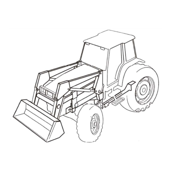
Page 6: Loader Identification Diagram
Loader Identification Diagram (HSL Model Shown) For further details refer to Loader Mainframe and Subframe diagrams. -
Page 7: Hydraulic Hose Kit Identification Diagrams
Hydraulic (Hose Kit) Identification Diagrams Hose Kit “A” Loader Powered by the tractor remotes. Consists of four hoses leading from loader tubing to tractor remote couplers Hose Kit “C” Loader operated by an external valve that is plumbed into the tractor hydraulic system. Consists of 4 hoses leading from loader tubing to external mounted valve plus the necessary fittings, hoses and adapter blocks... -
Page 8: Safety
• Never work beneath raised loader unless it is securely supported. The following are instructions for the Lift Lock Supports; Lift Lock Support Clevis Lift Cylinder Shaft LIFT LOCK INSTRUCTIONS TO ENGAGE SUPPORTS: TO DISENGAGE SUPPORTS: 1. RAISE LOADER PAST LEVEL 1. -
Page 9: Important Precautions
Important Precautions ELECTROCUTION HAZARD To prevent serious injury or death: Stay away from power lines and cables. Electrocution can occur with or without direct contact. CRUSHING HAZARD To prevent serious injury of death: Do not handle round bales or other shiftable objects unless loader is equipped with an attachment designed for this purpose. -
Page 10: Safety Decals
These decals are located as shown on the Decal Location diagram and the Sub-Frame Assembly diagram. OVERHEAD HAZARD STAY AWAY FROM UNDER LIFT To prevent serious injury or death: 1. Do not stand or work under raised loader, unless supported. 2. -
Page 12: General Instructions And Information
General Instructions and Information As with any piece of equipment, the care with which your loader is operated and maintained will greatly affect it’s life and the safety of the people using it. 1. Keep all pivots well lubricated for longer bushing life. Inspect every 500 hours of operation for wear. -
Page 13: Operation And Maintenance
Operation and Maintenance GENERAL Refer to tractor Operator’s Manual for Operating information on the tractor’s hydraulic system. Hydraulic systems using auxiliary valves should have them located for easy reach from the tractor seat. Hoses should be connected in such a manner that pushing forward on valve handles lowers the boom or dumps the bucket. -
Page 14: Operating Suggestions For Loading
Operating Suggestions for Loading When handling heavy loads, be sure to lower lift arms slowly. This is known as feathering the hydraulic lever. If load is lowered too fast and stopped suddenly, excessive shock loads are created which can damage loader or tractor. -
Page 15: Operating Suggestions For Backfilling
Operating Suggestions DO THIS! When backfilling approach pile with a flat bucket. Leave dirt in bucket. Dumping on each pass wastes time. NOT THIS! DO NOT use bucket in dumped position for bulldozing. This will only impose severe shock loading on the bucket cylinders and make it more difficult to maintain a level grade. -
Page 16: Attaching The Loader To Your Tractor
Attaching the Loader to Your Tractor Position the tractor as centrally as possible and drive, using lowest gear possible, into the loader frame until hoses can be connected. Couple up the hydraulic hose lines to the loader or tractor valve ensuring proper function (see Operator and Maintenance Section) NOTE: When mounting the loader for the first time, slowly work the cylinders back and forth, so that most of the air is... - Page 17 Attaching the Loader to Your Tractor When the hook is lined up, dump or roll back the bucket to lower or raise the subframe upright to align with the mounting boot. Continue to drive the tractor forward until the subframe uprights are seated in the boot. Secure the subframe uprights with the bolts and washers.
-
Page 18: Removing The Loader From Your Tractor
Removing the Loader from Your Tractor WARNING! When removing the loader, it must be fitted with a bucket or other suitable attachment to give the frame stability after removal. If this is not done, the frame will not remain standing. IMPORTANT! Always remove the loader on firm, level ground (away from children’s play areas and high traffic areas). - Page 19 Removing the Loader from Your Tractor Roll back the bucket slightly and simultaneously extend or retract the lift cylinders to free hooks from spools. Then slowly back up the tractor. Once the subframe is clear of the boot and the hook is clear of the mounting boss, roll back the bucket all the way.
-
Page 20: Trouble Shooting
PROBLEM Loader slow and/or will not dump. Loader chatters or vibrates when raising and lowering. Excessive movement at pivots Pump noisy Oil leaks. Insufficient lift capacity Slow leakdown. Excessive wear on bottom oil bucket and wear pads. Hydraulic cylinders inoperative. Pump operating continually on closed Tractor control valve relief stuck center tractor hydraulic system. -
Page 21: Tsl General Notes And Instructions
General Notes and Instructions to the Operator Regarding ALLIED TSL Loader Operations The true self levelling system (TSL) utilizes mechanical linkages to maintain bucket level while raising and lowering. The pivot plate weldment, levelling tubes and linkages have been developed to ensure that the bucket remains at the same position throughout its range of motion. -
Page 23: Sub-Frame Parts Table
595, S595, 595 TSL, & S595 TSL Item Part No. Description 25440 595 Sub Frame Weldment Left 25441 595 Sub Frame Weldment Right 25457 595 S Sub Frame Weldment Right 25458 595 S Sub Frame Weldment Left 110959 Hook Weldment... -
Page 25: Mainframe Parts Table
595, S595 Main Frame Parts Table Item Part No. Description 25442 595 Main Frame Weldment 25443 595 S Main Frame Weldment 24296 Quick Attach Weldment Left 24297 Quick Attach Weldment Right 112798 Tube Cross Qtach 108827 Pin Weldment 111231 Stand Weldment... -
Page 27: Tsl Mainframe Parts Table
595 TSL, S595 TSL Main Frame Parts Table Item Part No. Description 24729 595 TSL Mainframe 3.0 DIA. Lift 24737 S595 TSL Mainframe 3.0 DIA. Lift 24717 Quick Attach Left 24716 Quick Attach Right 112798 Cross Tube 108827 Pin Weldment... -
Page 28: Hydraulic Plumbing Diagram
595, S595 Hydraulic Plumbing Diagram... -
Page 29: Hydraulic Plumbing Parts Table
812128 811414 812069 11362 81592 81344 595, S595 Plumbing Parts Table Description 2.5 Dia. X 20.63 Cyl. Assy. Bucket 2.5 Dia. X 28.50 Cyl. Assy. Lift 3/8 x 12" Hose 3/4 MORB x 3/4 SWFJIC 3/8 x 18" Hose 3/4 MORB x 3/4 SWFJIC 3/8 x 22"... -
Page 31: Tsl Hydraulic Plumbing Parts Table
595 TSL, S595 TSL Plumbing Parts Table Item Part No. Description 24726 3.0 DIA x 22.0 Cyl. Assy. Bucket 24408 3.0 DIA x 28.5 Cyl. Assy. Lift 812069 Tee 3/4-16MJIC X 3/4-16 MJIC 811414 Elbow 90º 3/4-16 MORB to 3/4 MJIC 812128 Elbow 90º... -
Page 32: Hydraulic Cylinder Assembly
595, S595, 595TSL, S595TSL Hydraulic Cylinder Assembly Diameter Length of Stroke Retracted Length Extended Length Cylinder Assembly No. Seal Kit No. Shaft Diameter Item Description Head Plate Shaft Weldment Cylinder Tube Weld't Piston Half (wide) Piston Half (narrow) Self-Locking Nut... - Page 34 (403) 962-6991 SK, Regina (306) 781-2300 ON, Woodstock (519) 539-0435 ON, Jasper (613) 283-1758 QC, Dorion (450) 455-4840 “ Buhler Manufacturing a partnership” 1260 Clarence Ave Winnipeg, MB. R3T 1T2 Ph.: (204) 661-8711 Fax: (204) 654-2503 www.buhler.com U.S. WAREHOUSES NC, Dunn...
Need help?
Do you have a question about the Allied 595 and is the answer not in the manual?
Questions and answers
What tractors will the 595 loader fit?
The Buhler (Allied) 595 loader is compatible with Allis 180 and 185 tractors. It was also previously mounted on an IH 86 Hydro tractor.
This answer is automatically generated
Do you make the tractor mounting brackets to put a 595 loader on a John Deere 6403 farm tractor