Advertisement
Quick Links
Advertisement

Subscribe to Our Youtube Channel
Related Manuals for MyBinding CH-HANDYPADDER


Summary of Contents for MyBinding CH-HANDYPADDER
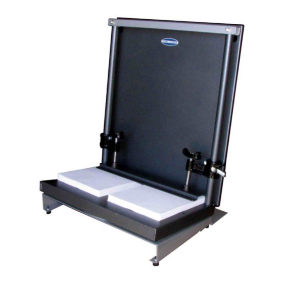
- Page 1 Challenge Handy Padder Portable Padding Press Instruction Manual...
- Page 2 The Challenge Machinery Company provides owner's manuals on its products solely as a courtesy to its customers. See the information below before using this manual. These manuals are for reference only. These manuals include products which are noncurrent, unsupported or no longer produced by The Challenge Machinery Company, and are provided solely as an accommodation to our customers.
-
Page 3: Warranty
1.0 Warranty * WARRANTY INFORMATION * PLEASE REVIEW THE ENCLOSED WARRANTY INFORMATION SHEET It is very important that you read and understand the conditions outlined in the Warranty Information Sheet attached to the outside of the shipping container of your machine. The Warranty Information Sheet must be filled out completely and returned to THE CHALLENGE MACHINERY COMPANY in order for the warranty to be issued for this machine. -
Page 4: Specifications
2.0 Specifications 16" / 40.6 cm Maximum Lift Height Maximum Lift Width 17-3/4" / 45 cm Lift Depth 4" to 13+" / 10 cm to 33+ cm Capacity Example 14,000 8-1/2 x 11" 20# bond Overall Base Area 20-15/16" / 53.2 cm Overall Height 26-3/16"... - Page 5 3.0 Installation and Operation 3.1 Installation Remove the Handy-Padder from its carton. Place it on a table or countertop. If placing on a counter, the silver anti-tip support should face toward the wall. 3.2 Operation 1. Jog piles for padding and place on the padder table as shown below. The vertical bars may be used as left/right jogging stops.
- Page 6 3. Rotate the table 180 in either direction until the table locks into place. 4. Remove the door by lifting it off its hanger screws. Apply padding compound to the exposed surfaces of the piles. 5. Allow the compound to dry for 10 to 20 minutes. Loosen the clamps and slide them out of the way.
- Page 7 3.3 Handy-Padder with Air Operation Operate the Handy-Padder with Air as described above. However, after applying the compound, switch on the fans. The switch is located on the right-hand side of the base of the machine. Drying may also be accelerated by placing the door back onto the screws with the bottom of the door resting on the door of the fan compartment as shown in the figure below.
- Page 8 4.0 Padding Tips Loading The Handy-Padder table rotates on a turnstile so the operator can work from one side of the padder. Counting Set the printer to offset each book at the output bin of the printer to keep each pad the same thickness.
-
Page 9: Parts List
Parts List 4.1 Main Assembly (without Air) - Page 10 4.2 Main Assembly (continued) ITEM PART NO. DESCRIPTION 65001 BASE 65002 TURNTABLE 65003 TABLE ASSEMBLY 65007 TIE BAR 65008 SUPPORT 65009 DOOR 65010 CLAMP A-11074 FOOT - RUBBER H-6417-5 NUT - 5/16-18 HEX H-6431-5 NUT - 5/16-18 ACORN CAP H-6910-102403 SCREW - #10-24 X 1/2 BUTTON HEAD CAP H-6918-102406 SCREW - #10-24 X 3/4 SOCKET HEAD CAP...
- Page 11 4.3 Main Assembly (with Air)
- Page 12 4.4 Main Assembly (with Air, continued) ITEM PART NO. DESCRIPTION 47092 GUARD - FAN 47136-4 EXTENSION SPRING 47163- GASKET 65001 BASE 65002 TURNTABLE 65003 TABLE ASSEMBLY 65007 TIE BAR 65009 DOOR 65010 CLAMP 65018 AIR BLOWER BASE 65022 SWITCH COVER A-11074 FOOT - RUBBER E-1140-11...
- Page 13 4.5 Wiring Diagram- E-3176 Rev. “A”...
- Page 14 Notes:...
- Page 15 F.1730 August 2015...
Need help?
Do you have a question about the CH-HANDYPADDER and is the answer not in the manual?
Questions and answers