Table of Contents
Advertisement
Advertisement
Table of Contents

Related Manuals for AirTouch ZoneTouch3

Summary of Contents for AirTouch ZoneTouch3
- Page 1 Installer Manual airtouch.net.au...
-
Page 3: Table Of Contents
6. Troubleshooting Liability Please read the instructions before installing this AirTouch Zoning Control System. Polyaire Pty Ltd does not accept any responsibility for loss or damage that may occur as a result of the incorrect installation of this AirTouch Control System. -
Page 5: Components
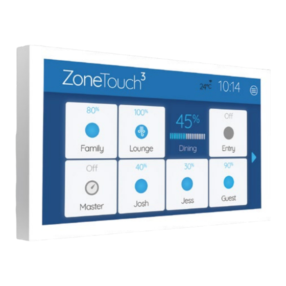
1. Components 1.1 Console Users can input control commands from the console to turn on or off a group/zone. It is used to input all parameters. The color LCD displays clock, zone, WiFi, temperature and other statuses. 1.2 Main Control Module and Extension Module (optional) Main control module (8 zones) and its optional extension module (extra 8 zones) control the... -
Page 6: Configuration
2. Configuration ZoneTouch 3 System is a star architecture system that allows communications between ZoneTouch 3 main control module, extension module, WiFi router (to connect to smart phones), up to 16 zone dampers, and up to two consoles. Figure below shows the connection of devices such as the WiFi router, a console, and eight dampers to the main module. - Page 7 Eight motorized dampers can be connected to the main control module. Nine dampers and above (up to 16) will need the extension module. The wiring of the ZoneTouch 3 system is straightforward. A cable with central latched plugs connects a motorized damper to the relevant output port clearly marked on the main or extension module.
- Page 8 Figure below shows the linking of the main module to the extension module, consoles, and smart phone. To Zone Dampers To Zone Dampers Extension Module Main Module Touch Screen 2 Home Router Touch Screen 1 Smart Phones NOTE: Install the console at least 20mm away from any other wall control to avoid potential interference.
-
Page 9: Pre-Installation
3. Pre-Installation Good planning leads to a successful zone system installation. Before installing and commissioning a zoning system, please complete the following listed tasks: Decide how many zones (dampers) are to be controlled in the system. Group zones according to customer’s requirements. Each group initially has one zone but can have up to a maximum of four zones (Example: There could be one or more zones going into a common area such as Kitchen/Dining or Family/Dining room). -
Page 10: Components Installation
4. Components Installation 4.1 Mount the main and/or extension modules (if using more than 8 zones) by screwing the boxes to a roof frame or Polyaire Diffusion Fitting (PDF). IMPORTANT: The modules should be kept away from hot places such as in between the sheet metal roof and the indoor unit where the extreme heat from the roof and indoor unit would... - Page 11 4.6 Connect the console to the ‘T’ port on the main module. If two consoles are used, connect one to T on the main module and the other to the extension module. 4.7 Connect the 24V AC transformer to screw terminals on the main control module.
- Page 12 4.9 Fit the Console to wall The plastic casing of the console consists of two halves. The front cover contains the PCB board along with the LCD/console. The back cover attaches to the wall as a mounting base. During the installation process the case will have to be opened to mount the console on the wall.
- Page 13 d. Cut the rectangular hole for the cable and fix the back base to the wall by using four screws on the marked positions. e. Retrieve the console cable (from main control module) out of the cable hole and plug it into the console. f.
- Page 14 g. Gently push the front cover against the wall and make sure the back of front cover is flush against the wall. And then push the front cover downwards with two figures holding the top side of the front cover where there are two slots till the two snap-ons click in.
-
Page 15: Recommended Commissioning Procedure
5. Recommended Commissioning Procedure There are two sets of settings, the installer’s and user’s. In the installer’s settings, the followings can be set: parameters, zone setting, spill/bypass, grouping and service. These settings are protected by a password which has default value Polyaire but can be changed. -
Page 16: Parameters
5.1 Parameters 5.1.1 Total Groups in the System For the purpose of group status display and spill zone calculation, the system needs to know the total number of groups to be installed. The factory default number is 8. IMPORTANT: This number must be equal to the total group number used in the system as planned in Pre-Installation process. -
Page 17: Installer Settings Password
5.1.2 Installer Settings Password The password is used to prevent unauthorized changing of the installer settings. To reset this password, touch the password edit field in the ‘Parameter’ screen, and then type in the new password and touch ‘Enter’ key to confirm the password change. 5.1.3 Damper RPM Setting ZoneTouch 3 can work with other dampers which are not made by Polyaire. -
Page 18: Zone Setting
5.2 Zone Setting Zone Setting... - Page 19 A zone can be marked as Disabled if the port is faulty. Then it will not be used by any group. The group used this zone before can choose another good zone. Electronic balancing feature of ZoneTouch 3 offers the flexibility of balancing the amount of airflow to each zone electronically.
-
Page 20: Grouping Zones
5.3 Grouping Zones For ease of control operation, multiple zones can be grouped together. The grouped zones are treated as one group with its own name and turned on or off together. Individual balanced damper position is not affected by grouping, which means zone balancing can be conducted before or after grouping. -
Page 21: Spill Or Bypass
5.4 Spill or Bypass Spill or bypass mode is a safety feature of the ZoneTouch 3 system to prevent pressure from building up and causing duct damage. This usually occurs if someone has turned off all groups while the A/C unit is pumping air into the system leading to a pressure build-up (and potential of duct puncture, blow-offs or joints splitting). - Page 22 IMPORTANT: Choose at least one group as spill group unless there is a permanent open zone used as spill zone. Otherwise, there will be no spill group when all zones are closed and damage may be caused by high pressure building up inside ducts if air conditioner is running. The Bypass and Spill cannot be set at the same time.
-
Page 23: Enabling/Disabling Service Reminder
5.5 Enabling/Disabling Service Reminder There is a built-in service reminder in the system for half year, one year and two years to automatically display an alert notifying customers that the air conditioning system is due for service. Installers can also use this feature to leave their details such as their names and contact number. -
Page 24: System Info
5.6 System Info Touching System Info menu will show product model, Device ID, current hardware and software versions of the system. If there is a new version, there will be a red dot on the Quick menu of the homepage. Following the red dot and prompts will bring up the update button for updating. -
Page 25: Setting Up Wi-Fi Connection
5.7 Setting up Wi-Fi Connection With WiFi connected to the home router which has internet access, ZoneTouch 3 will be able to update online. Go to WiFi Connection section in the quick access menu to connect the ZoneTouch 3 to the home router. The available WiFi networks will appear. Choose the correct one and key in the password to connect. -
Page 26: Testing Damper On/Off
5.8 Testing Damper On/Off Switch on the air conditioner. Enter the home screen of ZoneTouch 3 Touch the group buttons to turn groups on or off to check if the dampers are correctly connected by feeling the air at the outlet. The Turbo group can be tested by selecting the relevant chosen group as Turbo mode in the ‘Settings’... -
Page 27: Troubleshooting
6. Troubleshooting Problem Suggested Action Dampers have Check if LEDs on the main module light up for relevant zones when the zone dampers are being no response turned On/Off. If Green/Red LEDs are not ON for when turned the respective zone, the main module may be on or off faulty, replace it. - Page 28 Gepps Cross South Australia, 5094 accept any responsibility for loss or damage that Tel: (08) 8349 8466 Fax: (08) 8349 8446 may occur as a result of the incorrect installation or © Polyaire Pty Ltd 2021 operation of this AirTouch Control System.
Need help?
Do you have a question about the ZoneTouch3 and is the answer not in the manual?
Questions and answers