Advertisement
Available languages
Available languages
Quick Links
Phone: 1-877-PUMP-P2O (877-786-7726)
Web Site: http://parts2o.com
PUMP DISASSEMBLY
1.
Hazardous voltage.
Disconnect power to motor (See
Figure 1) before servicing pump.
Figure 1
2. Open faucets or lines to release all
pressure in system before proceeding.
3. Disconnect wires to pressure
switch.
NOTE: Mark wires for correct reassembly.
4. Remove pressure switch tube from
barbed fitting on pump body.
Remove pressure gauge and drain
plug and allow pump to drain.
5. Remove clamp.
6. Remove pump base mounting bolts.
Motor assembly and back half of
pump can now be pulled away from
pump front half. CAREFULLY
remove O-ring (See Figure 2).
1193 0794
Figure 2
CLEANING/REPLACING IMPELLER
NOTE: First, follow instructions under
"Pump Disassembly".
1. Remove five screws fastening dif-
fuser to seal plate; remove diffuser
(See Figure 3). Exposed impeller
can now be cleaned.
2. If impeller must be replaced, loosen
two machine screws and remove
motor canopy (See Figure 4).
Figure 3
1194 0794
be hazardous. To discharge capacitor,
hold insulated-handle screwdriver BY
THE HANDLE and short capacitor
terminals together. Do not touch metal
screwdriver blade or capacitor termi-
nals. If in doubt, consult a qualified
electrician.
3. Unscrew capacitor clamp and
remove capacitor. Do not discon-
nect capacitor wires to motor.
4. Slide 7/16" open end wrench in
behind spring loaded switch on
motor end of shaft; hold motor shaft
with wrench on shaft flats and
unscrew impeller by turning coun-
terclockwise when looking into eye
of impeller (see Figure 4).
Figure 4
5. To reinstall, reverse steps 1 thru 5.
6. See directions under "Pump
Reassembly".
REMOVING OLD SEAL
1. Follow instructions under "Pump
Disassembly."
2. Follow steps 1 through 5 under
"Cleaning/ Replacing Impeller."
3. Unscrew four nuts holding pump
back half to motor. Remove rotating
half of seal by placing two screw-
drivers under back half of pump
body and carefully prying up (See
Figure 5). Back half of pump body
will slide off shaft, bringing seal
with it.
For further operating, installation, or maintenance assistance:
1-877-PUMP-P2O
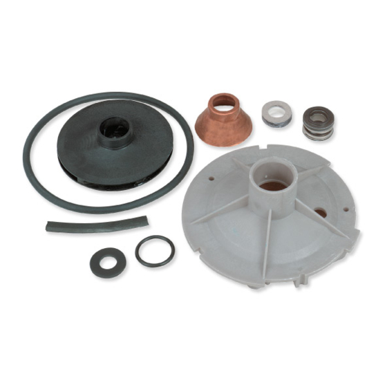
Jet Pump Overhaul Kit
FPP1511, FPP1512, FPP1513
753 0993
Capacitor voltage may
(1-877-786-7726)
Figure 5
IMPORTANT: Be sure you do not
scratch or mar shaft; if shaft is marred, it
must be dressed smooth with fine emery
or crocus cloth before installing new
seal. Do not reduce shaft diameter!
4. Place pump body half face down on
flat surface and tap out stationary
half of seal (See Figure 6).
Figure 6
INSTALLING NEW SEAL
1. Clean seal cavity in seal plate.
2. Wet outer edge of Rubber Cup on
ceramic seat with liquid soap. Be
sparing!
3. Put clean cardboard washer on seal
face. With thumb pressure, press
ceramic seal half firmly and square-
ly into seal cavity in seal plate (See
Figure 7). Polished face of ceramic
seat is up. If seal will not seat cor-
rectly, remove, placing seal face up
on bench. Reclean cavity. Seal
should now seat correctly.
Figure 7
P2O-30 (9/4/07)
479 0194 NF
477 0194NF
( continued )
Advertisement

Related Manuals for Parts2o FPP1511


Summary of Contents for Parts2o FPP1511
- Page 1 Jet Pump Overhaul Kit Phone: 1-877-PUMP-P2O (877-786-7726) FPP1511, FPP1512, FPP1513 Web Site: http://parts2o.com PUMP DISASSEMBLY Hazardous voltage. Disconnect power to motor (See Figure 1) before servicing pump. Figure 5 Figure 3 753 0993 IMPORTANT: Be sure you do not scratch or mar shaft; if shaft is marred, it...
-
Page 2: Pump Reassembly
Figure 10 shoulder. The carbon surface must remain clean or short seal life will result. Pump Brand For Use With Kit No.: FPP1511 FPP1512 FPP1513 Flotec FP4301, FP4312 FP4322 FP4322... - Page 3 18 19 Kit Contents FPP1511 FPP1511 FPP1512 FPP1513 FPP1500 Part Description Qty. 1/3 HP 1/2 HP 3/4 HP 1 HP (Universal) Water Slinger 17351-0009 17351-0009 17351-0009 17351-0009 17351-0009 Shaft Seal U109-6A U109-6A U109-6A U109-6A U109-6A Impeller J105-40PE J105-40PE J105-42PT J105-8PAN –...
-
Page 4: Démontage De La Pompe
Trousse de réparation des pompes à éjecteur DÉMONTAGE DE LA POMPE Tension danger- euse. Couper le courant alimentant le moteur (voir la Figure 1) avant d’intervenir sur la pompe. Figure 5 Figure 3 IMPORTANT : Faire bien attention de 753 0993 ne pas rayer l’arbre;... -
Page 5: Remontage De La Pompe
La surface en carbone doit rester propre, sinon la durée du joint sera raccourcie. Marques de pompes À utiliser avec les trousses numéro FPP1511 FPP1512 FPP1513 Flotec FP4301, FP4312 FP4322 FP4322... -
Page 6: Desensamblaje De La Bomba
Paquete de revisión para bombas de chorro DESENSAMBLAJE DE LA BOMBA Tensión peligrosa. Desconecte la fuente de alimenta- ción eléctrica al motor (Consulte la Figura 1) antes de realizar trabajos de reparación en la bomba. Figura 5 IMPORTANTE: Asegúrese de no rayar Figura 3 753 0993 ni estropear el eje;... - Page 7 La superficie de carbón debe permanecer limpia, de lo contrario se acortará la vida útil de la junta. Marca de la bomba Para usar con el Paquete No.: FPP1511 FPP1512 FPP1513 Flotec FP4301, FP4312 FP4322...
- Page 8 18 19 Contenu de la trousse Désignation FPP1511 FPP1511 FPP1512 FPP1513 FPP1500 Réf. des pièces Qté 1/3 ch 1/2 ch 3/4 ch 1 ch (Universel) Déflecteur d’eau 17351-0009 17351-0009 17351-0009 17351-0009 17351-0009 Joint de l’arbre U109-6A U109-6A U109-6A U109-6A U109-6A...