Table of Contents
Advertisement
Quick Links
Advertisement
Table of Contents

Subscribe to Our Youtube Channel
Related Manuals for Optoma BX-CTA16

Summary of Contents for Optoma BX-CTA16
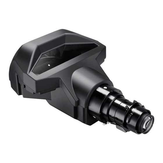
- Page 1 Installation Guide BX-CTA16 Ultra Short Throw Lens User manual...
-
Page 2: Table Of Contents
TABLE OF CONTENTS Safety precautions ..................................3 Identifying product versions ..............................4 List of components ..................................5 Required tools ....................................6 Setting the projector start mode ............................6 Removing the non-UST boresight plate ..........................8 Installing the UST lens boresight plate (LSM 1) ......................9 Installing the UST lens pogo pin adapter (LSM 2 ONLY) .................. -
Page 3: Safety Precautions
Trademarks Optoma and its logo is a registered trademark of Optoma Corporation. Optoma Europe Ltd is the licensee of the registered trademark. -
Page 4: Identifying Product Versions
Identifying product versions The UST lens kit is designed with two types of installation accessories in order to fit the different lens shift modules (LSM) on the projectors. These instructions contain installation steps for both types. Please check the projector’s boresight to identify the version of the lens shift module. Note: Make sure the projector is turned off before checking the boresight. -
Page 5: List Of Components
List of components Check to make sure the following items are included in the UST lens package. Both LSM 1 and LSM 2 accessories are included in the lens package. Contact your dealer if anything is missing. • UST Lens •... -
Page 6: Required Tools
• LSM 2 components Supporting system components Quantity UST lens pogo pin adapter Boresight extender (with red rubber ring) L shape socket tool (black) UST Lens Boresight extender L shape socket tool(black) pogo pin adapter (with red rubber ring) Required tools The following tools are required for installing the UST lens. - Page 7 5. A lens calibration is performed. 6. To turn off the projector, press the “Exit“ key on the remote control. 7. Switch off the AC power button. 8. Remove the power cord. Or if you do NOT have a non-UST lens for this projector, or are using a ZU860, please use one of the following steps.
-
Page 8: Removing The Non-Ust Boresight Plate
Removing the non-UST boresight plate To replace the projector with a UST lens boresight plate, complete the following steps. 1. Remove the non ultra-short throw (non-UST) lens. 2. Remove the screws securing the non-UST lens boresight plate with a Philips #2 screwdriver. LSM 1: three screws LSM 2: four screws Note:... -
Page 9: Installing The Ust Lens Boresight Plate (Lsm 1)
Installing the UST lens boresight plate (LSM 1) For type 1 lens shift module (LSM 1), you need to install a UST lens boresight plate in order to attach the UST lens to the projector. 1. Disconnect the lens cable from the small circuit board on the lens shift module. Note: Ensure the cable is not wrapped or pinched when replacing the lens boresight plate. -
Page 10: Installing The Ust Lens Pogo Pin Adapter (Lsm 2 Only)
Installing the UST lens pogo pin adapter (LSM 2 ONLY) For type 2 lens shift module (LSM 2), you need to install an UST lens pogo pin adapter in order to attach the UST lens to the projector. 1. Loosen the three screws on the UST lens pogo pin adapter with a Philips #2 screwdriver. The middle screw controls the lateral position of the circuit board on the adapter: •... - Page 11 counter-clockwise for at least 3 turns. 3. Tighten the side screws on the pogo pin adapter. 4. Tighten the middle screw on the pogo pin adapter. Note: Please tighten the side screws before tightening the middle screw.
-
Page 12: Mounting The Ust Lens Support System
Mounting the UST lens support system A support system is designed to go with the UST lens to provide additional support. 1. Place the lens on a cushioned surface to avoid damage. 2. To secure the lens bracket to the UST lens, install and tighten two M3 x L8 screws with a Philips #2 screwdriver. - Page 13 3. Place the projector upside down on a flat and clean surface. 4. To avoid the lens supporter touching the surface, rotate the adjustment feet counter-clockwise at least five turns. 5. To secure the angle bracket to the lens supporter, install one M3 x L8 hex screw and one M3 washer with a 2.5 mm allen key.
- Page 14 6. To mount the lens supporter to the bottom of the projecor, install and tighten two M6 x L22 hex screws and two M6 washers with a 5 mm allen key. 7. If using the lens supporter with a ceiling mount, make sure to leave at least 30 mm clearance space above the projector’s bottom intake vents.
- Page 15 8. Place the projector back to its original orientation. 9. Install the three boresight extenders. For LSM 1, face the socket heads of the extenders towards the projector. • For LSM 1 ONLY, face the socket heads of the extenders towards the projector. LSM 1: boresight extenders •...
-
Page 16: Initially Adjusting The Boresight Screws
Initially adjusting the boresight screws Before installing the UST lens, adjust the boresight screws by turning the boresight extenders clockwise or counter-clockwise. Once a lens is installed, the adjustment ranges for the boresight screws are limited. 1. Turn the boresight gears counter-clockwise to the end position with the boresight extenders. •... -
Page 17: Installing The Ust Lens
• Adjustment ranges for LSM 1 ONLY Key Note: 1 revolution = 1 complete rotation of the tool used (or the small gear you are turning) Adjustment ranges (in turns) for the boresight screws (LSM 1) Orientation Table Top 3 + 1/4 7 + 3/4 8 + 3/4 Portrait(L) - Page 18 2. Rotate the UST lens clockwise to lock the lens. To connect the lens bracket and the lens support assembly, install two M3 x L8 hex screws and two M3 washers with a 2.5 mm allen key. Do not fully tighten the screws.
-
Page 19: Adjusting The Image Position And Focus
Adjusting the image position and focus After the UST lens is installed, turn on the projector and adjust the image position. 1. Place the projector as close as possible to the screen. 2. Turn on the projector. 3. To display a test pattern, press the “Pattern “key on the remote control. The test image could be out of focus and the bottom edge may appear obscured or in dark. - Page 20 a. Press “Zoom“ keys to adjust the back focus until the screen center (point 5) is clear and sharp. b. Press “Focus“ keys to adjust the image focus until the screen corners (point 1, 3, 7, and 9) are clear and sharp.
-
Page 21: Adjusting The Boresight
Adjusting the boresight Boresight adjustment is needed if the image is still unsharp after the focus adjustment. The boresight adjustment tilts the lens holder to parallel the lens plane and the DMD plane to fully focus the image on the screen. -
Page 22: Finalizing The Image Adjustment
3. To focus the left bottom area of the screen (point 4 and 7), turn boresight screw B clockwise or counter- clockwise. 4. To focus the right bottom area of the screen (point 6 and 9), turn boresight screw C clockwise or counter-clockwise. -
Page 23: Removing The Ust Lens
Removing the UST lens Complete the following steps to remove the UST lens. 1. Turn off the projector. 2. Switch off the AC power button and remove the power cord. 3. For LSM 1, press the lens release button with a long neck screwdriver. For LSM 2, go to step 4 4. -
Page 24: Installing An Non-Ust Lens
Installing a non-UST lens To install a non-UST lens to the projector, complete following steps. 1. Remove the UST lens accessory installed on the projector and install the original boresight for the non- UST lens. Note: Refer to the images in the steps on page 5 to 8. •... -
Page 25: Ust Lens Specifications
UST Lens specifications Specifications of the UST lens 0.361 (120”) Throw ratio Focal length 9.49-9.55 F number Zoom ratio No zoom Throw distance 0.93-3.11 m 120” to 400” Screen size Lens configuration 3 group 23 elements Brightness ratio 70% (for reference) Net weight 2.715 kg...
Need help?
Do you have a question about the BX-CTA16 and is the answer not in the manual?
Questions and answers