
Related Manuals for Wilhelmsen UNITOR UWW-301


Summary of Contents for Wilhelmsen UNITOR UWW-301
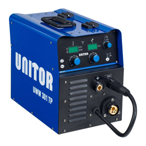
- Page 1 Instruction Manual UWW-301 TP WIRE WELDER UWW-301 TP Page 1 of 38 Revision: 1.0/June-/2020...
-
Page 2: Table Of Contents
TABLE OF CONTENTS INTRODUCTION ..................................... 3 INSTALLATION ...................................... 3 CONNECTIONS TO THE MAINS POWER SUPPLY ..........................3 FRONT PANEL......................................4 REAR PANEL ......................................4 PREPARING FOR MMA WELDING ................................ 4 PREPARING FOR TIG WELDING ................................6 PREPARING FOR MIG/MAG WELDING ..............................7 2.6.1 WIRE SPOOL POSITIONING...................................... -
Page 3: Introduction
INTRODUCTION INSTALLATION IMPORTANT! DANGER! Lifting and positioning This handbook must be consigned to the user prior to installation and commissioning of the unit. Retain these documents for future consultation. Use the handles and straps solely for manual lifting of the equipment. -
Page 4: Front Panel
FRONT PANEL 3. Welding power source ON/OFF switch. 4. Mains protection ON LED. This LED illuminates in case of an absence of a phase in the power supply line. 5. Power cable. Total length (including internal part): 3,5 m Number and cross section of wires: 4 x 1,5 mm Type of plug supplied: not supplied 1. - Page 5 Preparing for MMA (polarity to basic electrode) DANGER! Electric shock hazard! When the machine is switched on and set to work in MMA mode, its welding sockets are live and ready to strike the welding arc. Do not touch the conductive part of the electrode holder and metal parts at the same time with your hands.
-
Page 6: Preparing For Tig Welding
PREPARING FOR TIG WELDING Preparing for TIG (polarity for tungsten electrode) 1. Set the welding power source ON/OFF switch to “O” (unit switched off). 2. Plug the power cable plug into a mains socket outlet. 3. Choose the electrode based on the type of material and thickness of the workpiece to be welded. -
Page 7: Preparing For Mig/Mag Welding
PREPARING FOR MIG/MAG WELDING 2.6.1 WIRE SPOOL POSITIONING 1. Open the unit side door to gain access to the spool compartment. 2. Unscrew the cap of the spool holder. 2.6.2 POSITIONING THE WIRE IN THE WIRE FEEDER 1. Lower the wire feeder pressure devices. 3. -
Page 8: Connections To Sockets
7. Close the wire feeder pressure arms. 13. Open the gas solenoid valve by raising the lever (SEL1) located in the spool compartment: 8. Adjust the pressure system so that the arms press the wire with a force that does not deform it while also ensuring constant feed rate 14. -
Page 9: Commissioning
COMMISSIONING USER INTERFACE CODE SYMBOL DESCRIPTION This LED illuminates to show an anomaly in the operating conditions. See § 3.5 ALARM MANAGEMENT page 12. Illumination of this LED indicates the display of the average voltage and current value measured during the final moments of welding. - Page 10 Parameters/functions setting Manual MIG/MAG mode: the display shows the programmed voltage. MIG/MAG mode: the display shows “MMA”. TIG mode: the display shows “TIG”. Welding The display shows the effective voltage used when welding. Menu function The display shows the value of the parameter or function to be adjusted. The button selects the welding mode (MIG/MAG, MMA, TIG).
-
Page 11: Unit Power-Up
UNIT POWER-UP Set the welding power source ON/OFF switch to “I” to switch on the unit. The message appears for a few seconds on the following displays: D1-D2 AL.HEA. First power-up or power-ups following a RESET procedure The welding power source sets up for welding with the factory preset values. Subsequent power-ups The welding power source sets up for welding in the latest stable welding configuration that was active at the time of power-off. -
Page 12: Alarm Management
ALARM MANAGEMENT This LED illuminates if an incorrect operating condition occurs. An alarm message appears on the following display: D1-D2 Tab. 1 - Alarm messages MESSAGE MEANING EVENT CHECKS - Make sure that the power required by All functions are disabled. the welding process is lower than the Exceptions: maximum rated power output. -
Page 13: Welding Settings
WELDING SETTINGS TORCH TRIGGER MODES 2 STROKE LIFT-ARC TIG WELDING (2T) 1. Touch the workpiece with the torch electrode. 2. Slowly lift the torch to strike the arc. The welding current reaches the pre-set value, by way of an up slope time, if programmed. The current reaches the end current value in the time set in the down slope time parameter. -
Page 14: Selection Of The Welding Mode And Torch Trigger Procedure
SELECTION OF THE WELDING MODE AND TORCH TRIGGER PROCEDURE Use this button to select one of the following welding modes. Use this button to select one of the following torch trigger procedures. PROCEDURE MODE 2 STROKE 4 STROKE CONTINUOUS DC TIG ... -
Page 15: Welding Parameters
WELDING PARAMETERS INDUCTANCE Consequences of a higher value: WELDING CURRENT - "Softer welding". Output current value during welding. - Less spatter. - Less positive starting. HOT-START Consequences of a lower value: This parameter aids electrode melting at the time of arc striking. - "Harder welding". -
Page 16: Electrode Welding (Mma)
ELECTRODE WELDING (MMA) This button serves to select the following welding mode: MMA The message appears on the following displays: D2 4.5.1 PARAMETERS SETTING: WELDING CURRENT POT2 Using the potentiometer, edit the value of the parameter. The value appears on the following display: D1 PARAMETER DEFAULT WELDING CURRENT... -
Page 17: Mig/Mag Welding
MIG/MAG WELDING This button serves to select the following welding mode: MIG/MAG 4.7.1 PARAMETERS SETTING: MIG/MAG WELDING VOLTAGE POT3 Using the potentiometer, edit the value of the parameter. The value is saved automatically. PARAMETER DEFAULT MIG/MAG WELDING 10.0 V 40.0 V VOLTAGE 4.7.2 PARAMETERS SETTING: WIRE FEED RATE... -
Page 18: Technical Data
TECHNICAL DATA Waste electrical and electronic equipment (WEEE) Electromagnetic compatibility (EMC) Directives applied Low voltage (LVD) Restriction of the use of certain hazardous substances (RoHS) Construction standards EN 60974-1; EN 60974-5; EN 60974-10 Class A Equipment compliant with European directives in force Equipment suitable in an environment with increased hazard of electric shock Conformity markings Equipment compliant with WEEE directive... - Page 19 40 % (40° C) 8.0 A 60 % (40° C) 8.2 A 100 % (40° C) 8.8 A 50 % (40° C) 6.2 A Maximum effective supply current 60 % (40° C) 6.4 A 100 % (40° C) 6.8 A 35 % (40°...
-
Page 20: Spare Parts
SPARE PARTS UWW-301 TP Page 20 of 38 Revision: 1.0/June-/2020... - Page 21 N° CODICE DESCRIZIONE 011.0009.0102 FAN SUPPORT 011.0006.0031 HANDLE 011.0009.0110 INTERNAL FAN SUPPORT 011.0006.0006 PLASTIC HINGE 032.0001.8215 PRIMARY RECTIFIER 011.0001.0681 UPPER COVER 050.0001.0084 FAN CONTROL BOARD 045.0006.0053 COPPER BRACKET (POSITIVE POLE) 041.0004.0301 HALL SENSOR 045.0006.0052 COPPER BRACKET (NEGATIVE POLE) 032.0002.2403 DIODE 050.0003.0044 SNUBBER BOARD 045.0006.0080...
-
Page 22: Wire Feed Motor
WIRE FEED MOTOR UWW-301 TP Page 22 of 38 Revision: 1.0/June-/2020... -
Page 23: Wire Feeder Rolls
N° CODICE DESCRIZIONE 002.0000.0205 COMPLETE PRESSURE ARM 002.0000.0203 COMPLETE PRESSURE DEVICE 002.0000.0201 MOTOR COIL 002.0000.0259 INLET GUIDE WITH SOFT LINER 002.0000.0202 FEED PLATE 002.0000.0266 GUARD SAFETY KIT 002.0000.0212 INSULATION MOUNTING KIT 002.0000.0209 GEAR ADAPTOR FEED ROLL 002.0000.0210 MAIN GEAR DRIVE 002.0000.0207 SCREW 002.0000.0208... - Page 24 WELDING SETTINGS GUIDE UWW-301 TP Page 24 of 38 Revision: 1.0/June-/2020...
-
Page 25: Routine Maintenance
ROUTINE MAINTENANCE Checkpoint Action Interval Primary plug Check connections 3 months or more and socket and stretch relief often if needed Check for damage and replace if 3 months or more Primary cable necessary often if needed Primary cable Check for damage 3 months or more stretch relief and tightness... - Page 26 TORCH 1. Check wire feed liner for damage or wear at regular intervals. This is especially important for the non-iron liner which may wear quickly if used for extensive shelf-shield welding. 2. Replace worn contact tips as required. A variable arc is a typical symptom of a worn contact tip. 3.
-
Page 27: Ordering Information Basic Accessories
ORDERING INFORMATION BASIC ACCESSORIES Product Number Product Name Power Source 301301 UWW-301 TP WIRE WELDER Accessories for Selfshield Wire Welding and Stick Welding 670410 ACCESSORIES KIT F/UWW-301 TP WIRE WELDER Consumables for Selfshield Wire Welding - Carbon Steel 722228 MS-W-203 SELFSHIELD Consumables for Selfshield Wire Welding - Stainless Steel 699492 TENSILE-W-228 SELFSHIELD... -
Page 28: Tig And Wire Torches With Spares
TIG AND WIRE TORCHES WITH SPARES TIG WELDING TIG torch T-200 complete with long back-cap, 2,4mm electrode, collet and nozzle Order number 197-200000 Pos. Order number Unit Product description 197-551192 Short back-cap 197-551200 Long back-cap 197-613767 Heat shield 197-551168 Collet 1.6mm 197-551150 Collet 2.4mm 197-551184... - Page 29 GAS SHIELDED WIRE WELDING T-400 torch for gas shielded wire welding, complete with contact tip 1,0-1,2mm and Teflon liner. Order number 193-607451 6 inside Pos. Order number Unit Product description 193-551192 Gas nozzle for torch 193-613766 Nozzle insulator 5 pcs 193-594622 Contact tips 0.8 mm 10 pcs 193-594630...
- Page 30 SELFSHIELD WIRE WELDING T-350 torch for gasless welding with self-shielded wire, complete with 1,2mm contact tip and 1,0-1,4mm red coated steel liner. Order number 193-750179 Pos. Order number Unit Product description n.a. End of swan neck on torch 193-594614 Torch liner, Steel for 0.6-1.0 mm wire (blue) 3.0 m long 193-607457 Torch liner, Steel for 1.0-1,4 mm wire (red) 3.0 m long 193-777846...
-
Page 31: Electrical Diagram
ELECTRICAL DIAGRAM 10.1 UWW 301 TP UWW-301 TP Page 31 of 38 Revision: 1.0/June-/2020... - Page 32 UWW-301 TP Page 32 of 38 Revision: 1.0/June-/2020...
-
Page 33: Safety Instructions
SAFETY INSTRUCTIONS Arc Welding Hazards The safety information given below is only a summary of the more complete safety information found in the Safety Standards listed in Section 1-5. Read and follow all Safety Standards. Only qualified persons should install, operate, maintain, and repair this unit. During operation, keep everybody, especially children, away. - Page 34 FUMES AND GASES can be hazardous. Welding produces fumes and gases. Breathing these fumes and gases can be hazardous to your health. Keep your head out of the fumes. Do not breathe the fumes. If inside, ventilate the area and/or use exhaust at the arc to remove welding fumes and gases.
- Page 35 CYLINDERS can explode if damaged. Shielding gas cylinders contain gas under high pressure. If damaged, a cylinder can explode. Since gas cylinders are normally part of the welding process, be sure to treat them carefully. Protect compressed gas cylinders from excessive heat, mechanical shocks, slag, open flames, sparks, and arcs.
- Page 36 EMF Information Considerations about welding and the effects of low frequency electric and magnetic fields. Welding current, as it flows through welding cables, will cause electromagnetic fields. There has been and still is some concern about such fields. However, after examining more than 500 studies spanning 17 years of research, a special blue ribbon committee of the National Research Council concluded that: “The body of evidence, in the committee’s judgment, has not demonstrated that exposure to power-frequency electric and magnetic fields is a human-health hazard.”...
- Page 37 DECLARATION OF CONFORMITY UWW 301TP We hereby state that the machine type: 2014/30/UE (EMC) is in compliance with the directives: 2014/35/UE (LVD) 2011/65/UE (RoHS2) EN IEC 60974-1:2018+A1:2019 EN IEC 60974-5:2019 and that the following standards apply: IEC 60974-10:2014+A1:2015 EN 60974-10:2014+A1:2015 WECO srl Belvedere, 20/07/2019 Via S.
- Page 38 Please use these Unitor products exclusively for the purpose indicated by WSS and only if the operator fully understands current practices and procedures. If any further information or assistance is required please contact your local WSS specialist. www.wilhelmsen.com UWW-301 TP Page 38 of 38 Revision: 1.0/June-/2020...
Need help?
Do you have a question about the UNITOR UWW-301 and is the answer not in the manual?
Questions and answers