Table of Contents
Advertisement
Advertisement
Table of Contents

Related Manuals for Wilhelmsen UNITOR UPC 310 ML


Summary of Contents for Wilhelmsen UNITOR UPC 310 ML
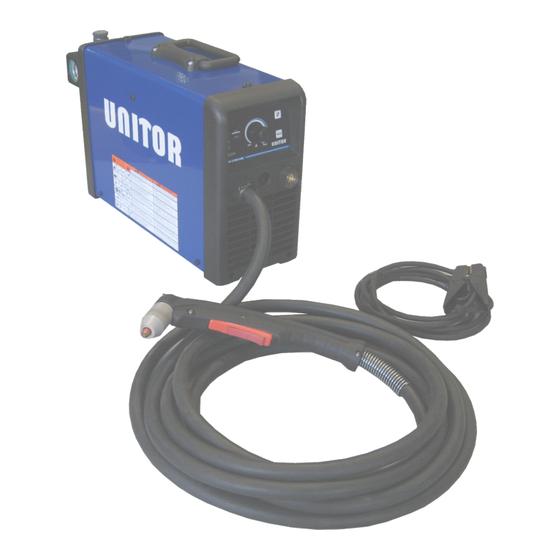
- Page 1 Instruction manual UPC 310 ML Air Plasma Cutter...
- Page 2 Revision summary Rev. No. Version Date issued 6938700000 April 18, 2018...
-
Page 3: Table Of Contents
CONTENTS 1.Safety instructions 2.Technical data 3.Installation 4.Operating instructions 5.Torch parts 6.Maintenance 7.Trouble shooting 8.Cutting/thickness characteristics 9.Wiring diagram 10.Parts list DELIVERY UPC-310ML Air Plasma Cutter 192-310331 delivery consist of: Machine supply complete with 3,5m primary cable 2+G x 2,5mm Torch with 6m cable (connected directly to the machine) Return clamp with 6m cable with Dix25 Initial supply consumables kit of 2 x Electrode, 2 x Tip Drag, 1 x Cartridge Air regulator with filter and water separator mounted on the machine... -
Page 4: Safety Instructions
1 SAFETY INSTRUCTIONS ELECTRIC SHOCK CAN KILL - Disconnect the power supply before working on the plasma machine. - Do not work with deteriorated cable sheaths. - Do not touch bare electrical parts. - Ensure that all the panels covering the plasma machine are firmly secured in place when the machine is connected to the mains supply. -
Page 5: Technical Data
PREVENTION OF BURNS To protect your eyes and skin from burns and ultraviolet rays: - wear dark glasses. Wear suitable clothing, gloves and footwear. - use masks with closed sides, having lenses and protective glass according to standards (degree of protection DIN 10). -
Page 6: Installation
3 INSTALLATION WARNING: This Class A equipment is not intended for use in residential locations where the electrical power is provided by the public low-voltage supply system. There may be potential difficulties in ensuring electromagnetic compatibility in those locations, due to conducted as well as radiated disturbances. This equipment is complying with IEC 61000-3-12 and It can be connect to a public and private low voltage system. -
Page 7: Operating Instructions
4 OPERATING INSTRUCTIONS Place machine as far away from where cutting takes place as possible. Use all of the 6m torch length. This is to prevent the fumes produced by cutting from being sucked into machine by the cooling fans through the front and side ventilation openings. - Page 8 For the number reference below, refer to the Front Panel Description: 1.Turn the switch on the back panel to ON position. 2.The green led (5) will light up (Unit live). 3.The green led (1) will light up to indicate the presence of compressed air in the air circuit. The red led (2) is illuminated and the unit is now in STAND-BY.
- Page 9 CUTTING TECHNIQUE For best performance and life expectancy, always use the correct and original parts for cutting torch. 1.Install the cutting tip and set the output current. 2.Hold the torch away from your body. 3.Slede the trigger release toward the back of the torch handle while simultaneously squeezing the trigger.
-
Page 10: Torch Parts
5 TORCH PARTS DESCRIPTION PRODUCT NUMBER COMMENTS TORCH HEAD FOR UPC-310ML 310333 1 PCS ELECTRODE FOR UPC-310ML 310334 5 PCS START CARTRIDGE FOR UPC-310ML 310335 1 PCS TIP DRAG CUTTING FOR UPC-310ML 310336 5 PCS SHIELD CUP BODY FOR UPC-310ML 310337 1 PCS TORCH WITH 6M CABLE FOR UPC-310ML... -
Page 11: Troubleshooting
lower end fittings for free motion. Replace if necessary. 5. Pull the electrode straight out of the torch head. Check the face of the electrode for excessive wear. Refer to the following figure. 6. Re-install the electrode by pushing it straight into the torch head until it clicks. 7. - Page 12 DUTY CYCLE AND EXCESSIVE TEMPERATURE The Led indicator light (3) blink: 1. This is indicating the unit has exceeded the Duty Cycle. The duty cycle is the percentage of use of the welding machine in 10 minutes which the operator must respect to avoid the power supply output blocking due to exceeding working temperature.
-
Page 13: Cutting/Thickness Characteristics
8. CUTTING / THICKNESS CHARACTERISTICS Characteristics Thickness/ Cutting speed PLASMA 30 I2 = 230V - 30A 1torch SL100 I2 = 115V - 25A 1torch SL100 1500 1400 1300 1200 Fe C 1100 1000 Thickness (mm) Pressure = 4,8 bar Flow = 90 l/min 230V 1-Phase, 30A 115V 1-Phase, 25A Thickness... -
Page 14: Wiring Diagram
9. WIRING DIAGRAM... -
Page 15: Parts List
10. PARTS LIST DESCRIPTION PRODUCT DESCRIPTION PRODUCT NUMBER NUMBER Handle 66103400 Knob 66046700 Cover 620576U0 Front label 66139800 Panel 620357U0 Front panel support 620356U0 Switch 64774000 Potentiometer 61107400 Regulating filter support 620297R0 PCB Front panel 61223800 Regulating filter 63055000 XL out 61247800 Manometer 63053000... - Page 16 DECLARATION OF CONFORMITY According to The Low Voltage Directive 2014/35/EU The EMC Directive 2014/30/EU The RoHS Directive 2011/65/EU Type of equipment Plasma equipment Type of designation 601453000L – UPC310 MULTI-LINK Brand name or trade mark UNITOR Manufacturer or his authorized representatives established within the EEA: Name, address, phone, website: STEL s.r.l Via Del Progresso 59;...
Need help?
Do you have a question about the UNITOR UPC 310 ML and is the answer not in the manual?
Questions and answers