
Related Manuals for EMH ITZ

Summary of Contents for EMH ITZ
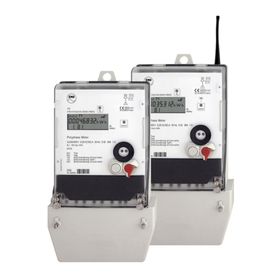
- Page 1 Product manual for the digital tariff meter ITZ Installation I Device description I Operation Edition: 25.11.2008 ITZ-PHB-E-1.00...
- Page 2 EMH. All of the trademarks named in this manual are the property of EMH Elektrizitätszähler GmbH & Co KG or the respective title holders.
-
Page 3: Table Of Contents
Contents page Prologue ......................6 Safety tips ......................6 Maintenance- and guarantee tips ..............6 Mounting and installation ................7 Mounting the meter ..................7 Connecting the meter ..................7 Terminal blocks....................8 2.3.1 Transformer operated meter ................8 2.3.2 Direct connected meter 60 A ................ - Page 4 Figure index Table 1: Housing- and display elements ................. 12 Table 2: Technical data ....................13 Table 3: Specifications of RS232 ..................15 Table 4: Specifications of RS485 ..................16 Table 5: Specifications of CL0 ..................17 Table 6: Specifications of inputs ..................18 Table 7: Specifications of outputs ...................
- Page 5 PTB (German certified body) Reactive power Positive reactive power Positive reactive energy Negative reactive energy (customer exports to utility) Measuring of absolute value of R Real Time Clock Interface accord. to DIN 43 864 raconet radio readout system of EMH...
-
Page 6: Prologue
1 Prologue In this manual, all design variants of the ITZ meter are described. Please note, that the meters can be designed differently regarding for example configuration, interfaces, in-/outputs etc. It is therefore possible that meter features are described in this manual which do not apply to the meter(s) used by you. -
Page 7: Mounting And Installation
2 Mounting and installation 2.1 Mounting the meter Meters form the series ITZ are suitable for wall mounting in accordance with DIN 43 857-2. Figure 1: Meter dimensions 2.2 Connecting the meter When connecting the meter it is very important to take notice of the connection diagram... -
Page 8: Terminal Blocks
2.3 Terminal blocks 2.3.1 Transformer operated meter Current Voltage Auxiliary terminals terminals terminals 9-block: 3.2 x 3 Terminal dimensions 12-block: 3 W x H (d) mm Max. connection- cross section (mm²) Maximum torques for terminals (Nm) Head/size of thread slot/M4 PZ1/M4 slot/M3 Figure 3: Terminal block for transformer operated meter... -
Page 9: Direct Connected Meter 100 A
2.3.3 Direct connected meter 100 A Voltage and auxiliary Current terminals terminals Terminal dimensions W x H (d) mm Max. connection- cross section (mm²) Maximum torques for terminals (Nm) Head/size of thread PZ2/M6 slot/M3 For testing the device the voltage path is interrupted by the path separator. -
Page 10: General Features
3 General features Direct connected or transformer operated meter for measuring active energy Registration of the energy can be parameterised at the factory as follows: Measuring of +A with non-reverse ratchet Measuring of +A and -A Measuring of absolute value of A Measuring of +R with non-reverse ratchet Measuring of +R and -R Measuring of absolute value of R... -
Page 11: Standards And Regulations
4 Standards and regulations DIN EN 50470-1 Electricity metering equipment (a.c.) - Part 1: General requirements, tests and test conditions - Metering equipment (class indexes A, B and C) DIN EN 50470-3 Electricity metering equipment (a.c.) - Part 3: Particular requirements - Static meters for active energy (class indexes A, B and C) DIN EN 60529... -
Page 12: Housing-, Operating- And Display Elements
5 Housing-, operating- and display elements Figure 6: Housing-, operating- and display elements Description Function Meter cover Test-LED Meter test LC-display Display of measured values and status information Operation of this button transfers Parameterisation button the meter into the parameterization mode (found under the meter cover Mechanical call-up button Call-up of the display contents... -
Page 13: Technical Description
6 Technical description 6.1 Technical data Voltage 4-wire meter 3x230/400 V, 3x220/380 V, 3x58/100 V, 3x63/110 V, 3x115/200 V, 3x127/220 V, 3x132/230 V Current 5(60) A, 5(85) A, 5(100) A, 10(60) A, 10(65) A, 10(100) A; 5II1 A, 1(6) A, 5 A Frequency 50 Hz, 60 Hz Accuracy... -
Page 14: Functional Circuit Diagram
Tariff switching can be parameterised, one tariff is always active. External tariff control is possible; thereby the internal tariff control is automatically deactivated. The ITZ has separate daily switching clocks for weekdays and holidays. -
Page 15: Data Interfaces
6.4 Data interfaces The data readout takes place according to 62056-21 via: optical data interface D0 electrical data interface (RS232, RS485 or CL0) raconet radio interface 6.4.1 Optical data interface D0 The D0-interface is designed according to IEC 62056-21 with Mode C. The following baud rates can be set: 300, 1200, 2400 or 4800 baud. -
Page 16: Electrical Data Interface Rs485
6.4.3 Electrical data interface RS485 The electrical interface (galvanically de-coupled) is found at the additional terminals under the sealable terminal cover (see connection diagram). The electrical interface RS485 is a symmetrical two wire interface and is designed in accordance with TIA/EIA-485 / ITU-T V.11. Up to 32 meters can be connected to a meter modem with RS485-interface. -
Page 17: Electrical Data Interface Cl0 (Cs)
6.4.4 Electrical data interface CL0 (CS) The electrical interface CL0 (galvanically de-coupled) is found at the additional terminal under the sealable terminal cover (see Figure 3 on page 8). The CL0 interface conforms to DIN 66348, Part 1. It is a passive two wire interface, i.e. possesses no own power source. -
Page 18: Inputs
Table 6: Specifications of inputs 6.6 Outputs The ITZ can be equipped with a maximum of 3 outputs: max. 3 as S0 output according to DIN 43 864 or max. 2 relays (make contact [NO]) resp. a high load relay (make contact [NO]) or max. -
Page 19: Sealable Meter Cover
6.7.2 Sealable meter cover The meter cover is made of crystal clear polycarbonate. The window area is transparent and the remaining cover surface has an eroded structure. The meter cover is hung at the top of the baseplate and fastened at the bottom with two sealed screws. Figure 10: Meter cover 6.7.3 Sealable terminal cover The terminal cover is made of grey polycarbonate. -
Page 20: Operating The Meter
7 Operating the meter 7.1 Operation modes 7.1.1 Parameter status (PAR-Status) The PAR-Status is used for configuration of the meter at the factory. For activation of this mode press the PAR-Status button. This button is found on the meters main PC-Board and is protected by a seal. -
Page 21: Display
7.2 Display The ITZ has a liquid crystal display (LCD). Figure 12: Layout of the display Description Phase display, phase sequence identifier Display of the active tariff Display, in which quadrant the meter is measuring Quadrant +P / +Q Quadrant -P / +Q... -
Page 22: Installation Error Recognition
7.2.1 Installation error recognition The ITZ offers the following possibilities for installation error recognition which are displayed with the help of the LCD segments „L1”, „L2” and „L3”: Phase display (U1, U2, U3) The display of the symbols L1, L2 and L3 signalises that voltage is applied at all individual. - Page 23 Examples: Case Display > 0, A < 0 +P static, L2 and -P flash +A is registered < 0, A > 0 -P static, L3 and +P flash -A is registered > 0, A and A < 0 +P static, L1, L3 and -P flash +A is registered lAl - Absolute meter If at least one phase is negative then in addition to the energy direction arrow...
- Page 24 < 0 +R is registered Phase failure recognition The ITZ registers the date and time of the voltage failures and also the date and time of the voltage return for every phase in the following registers: Voltage failure Voltage return C.51.1*VV...
-
Page 25: Manipulation Recognition
Manipulation event a) Terminal cover monitoring If the ITZ is in normal operation then every attempt to open the terminal cover is registered with the date and time. If the meter has a buffer battery the registration can also take place in a no-voltage condition. A manipulation of the terminal cover is signalised by a „hand symbol“... - Page 26 Reset of the manipulation register and creation of pre-values a) Reset when reading out via the optical interface D0 With a readout via the optical interface D0 the „hand symbol“ in the display or an activated alarm is deleted. Note: No pre-value is formed. b) Reset with a remote readout via the electrical interface The reset via the electrical interface takes place analogue to the reset via the optical interface.
-
Page 27: Display Control
7.3 Display control 7.3.1 Display control (Firmware 4.XX) Control of the display takes place principally via the call-up button [A]. Certain functions such as carrying out a manual reset, setting the data and time etc. require the operation of the reset button [R], which can be locked with a seal. For control of the display the following applies: Short keypress (<... -
Page 28: Display Control (Firmware 5.Xx And 6.Xx)
7.3.2 Display control (Firmware 5.XX and 6.XX) Control of the display takes place principally via the call-up button [A]. Certain functions such as carrying out a manual reset, setting the data and time etc. require the operation of the reset button [R], which can be locked with a seal. For control of the display the following applies: Short keypress (<... -
Page 29: Special Features
I R I=IR1I+IR2I+IR3I 8.2 Registration of instantaneous values The ITZ meter can register active power P, reactive power Q, voltage U (per phase) and current I (per phase) and display with the following digitness (integer digits/decimal digits [Unit]): U = 3.1 [V]... -
Page 30: Meter Readout
9 Meter readout 9.1 Communication software The standard communication software for the ITZ is the EMH-COM or EMH-COMBI-MASTER 2000. Figure 15: EMH-COMBI-MASTER 2000 With the program you can carry out the following: Read out the output lists Set the clock... -
Page 31: Appendix
The Object-Identification-System OBIS is described in IEC 62056-61 and is used for identification of measured values, e.g. electricity, water, gas and heat. The OBIS-code system is divided into the value groups A to F. The ITZ provides the groups C to F. - Page 32 Bedeutung [*F] Tariff 2 [*F] Tariff 3 [*F] Tariff 4 Instantaneous value current phase 1 Instantaneous value current phase 2 Instantaneous value current phase 3 Instantaneous value voltage phase 1 Instantaneous value voltage phase 2 Instantaneous value voltage phase 3 Instantaneous value active power total Instantaneous value reactive power total Manufacturing number...
-
Page 33: Ec Declaration Of Conformity
10.2 EC Declaration of conformity acc. to EMC Directive 2004/108/EG acc. to Measuring Instruments Directive 2004/22/EG The manufacturer EMH Elektrizitätszähler GmbH & Co KG Südring 5 19243 Wittenburg GERMANY certifies that following product Product designation: Electricity meter ITZ… Type designation: conforms to above mentioned directives, including all amendments, which are valid at the moment of issuing this declaration.
Need help?
Do you have a question about the ITZ and is the answer not in the manual?
Questions and answers