
Subscribe to Our Youtube Channel
Related Manuals for Axiom DEMO9S08SE8

Summary of Contents for Axiom DEMO9S08SE8
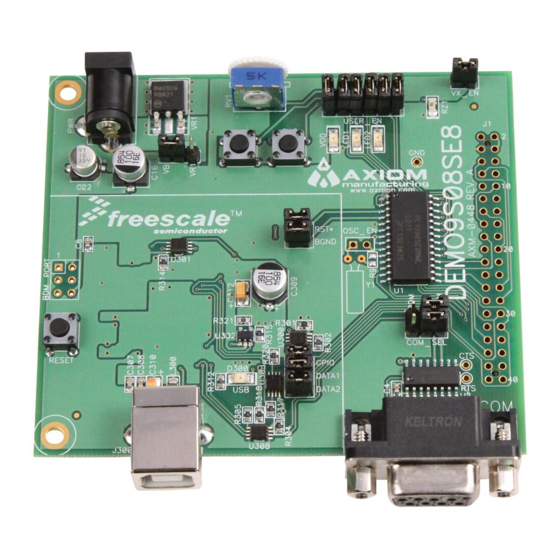
- Page 1 D O C - 0 4 4 8 - 0 1 0 R E V DEMO9S08SE8 Demonstration Board for Freescale MC9S08SE8 Microcontroller USER GUIDE www.axman.com Email: Support: support@axman.com...
-
Page 2: Table Of Contents
D E M O 9 S 0 8 S E 8 J U L Y 2 9 , 2 0 0 8 U S E R G U I D E CONTENTS CAUTIONARY NOTES ......................4 TERMINOLOGY.........................4 FEATURES ..........................5 REFERENCES ...........................6 GETTING STARTED........................6 SOFTWARE DEVELOPMENT ....................6 MEMORY MAP ..........................6... - Page 3 D E M O 9 S 0 8 S E 8 J U L Y 2 9 , 2 0 0 8 U S E R G U I D E FIGURES Figure 1: BDM Port ........................7 Figure 2: PWR_SEL Option Header ...................8 Figure 3.
-
Page 4: Cautionary Notes
1) Electrostatic Discharge (ESD) prevention measures should be used when handling this product. ESD damage is not a warranty repair item. 2) Axiom Manufacturing does not assume any liability arising out of the application or use of any product or circuit described herein; neither does it convey any license under patent rights or the rights of others. -
Page 5: Features
Development of applications is quick and easy with the integrated USB-BDM, sample software tools, and examples. An optional BDM_PORT port is also provided to allow use of a BDM_PORT cable. A 40-pin connector allows connecting the DEMO9S08SE8 board to an ex- panded evaluation environment. -
Page 6: References
G U I D E REFERENCES Reference documents are provided on the support CD in Acrobat Reader format. DEMO9S08SE8_UG.pdf DEMO9S08SE8 User Guide (this document) DEMO9S08SE8_SCH_C.pdf DEMO9S08SE8 Board Schematic, Rev. C GETTING STARTED To get started quickly, please refer to the DEMO9RS08SE8 Quick Start Guide. This quick start will help the user connect the board to a PC, install the correct version of CodeWarrior Development Studio, and run a simple demo program. -
Page 7: Development Support
NOTE: This header is not installed in default configuration. POWER The DEMO9S08SE8 is designed to be powered from the USB_BDM during application devel- opment. A 2.0mm barrel connector has been applied to support stand-alone operation. In ad- dition, the board may be powered through connector J1. The board may also be configured to... -
Page 8: Power Select
D E M O 9 S 0 8 S E 8 J U L Y 2 9 , 2 0 0 8 U S E R G U I D E When using the integrated USB-BDM, the board draws power from the USB bus. Total cur- rent consumption of the board and connected circuitry, therefore, must be limited to less than 500mA. -
Page 9: Vx_En
D E M O 9 S 0 8 S E 8 J U L Y 2 9 , 2 0 0 8 U S E R G U I D E The on-board voltage regulator (VR1) accepts power input through a 2.0mm barrel connector (PWR). -
Page 10: Low Voltage Detect
Manual for details on configuring LVD operation. TIMING By default, the DEMO9S08SE8 uses timing provided from an internal 32 kHz frequency refer- ence and an internal frequency-locked loop (FLL). The FLL output is trimmable to ± 0.2% of nominal. Refer to the MC9S08SE8 Reference Manual for further details on clock operation. -
Page 11: Virtual Serial Port
J1-5 PTB0/KBIP4/RXD/ADP6 J1-7 Virtual Serial Port The DEMO9S08SE8 provides a virtual serial port through the USB-BDM. Use of the virtual serial port requires the P&E Toolkit. The Toolkit is available on the DVD supplied with the demo board. COM_SEL The COM_SEL option header select between the virtual serial port implemented through the USB-BDM or the RS-232 PHY. -
Page 12: User Options
1, 6 USER OPTIONS The DEMO9S08SE8 includes various input and output devices to aid application development. User I/O devices include 2 momentary pushbutton switches, 2 green LEDs, 1 potentiometer, and 1 phototransistor. Each device may be enabled or disabled individually by the USER_EN option header. -
Page 13: I/O Port Connector
Disable RV1 PTA0/ADP4 Enable RZ1 Disable RZ1 PTA1/ADP5 I/O PORT CONNECTOR This port connector provides access to DEMO9S08SE8 I/O signals. Signal positions not shown listed are not connected on the board. Figure 6: MCU I/O Port Connector PTA5/IRQ/TCLK/RESET* PTA5/IRQ/TCLK/RESET* PTB1/KBIP5/TXD/ADP7...
Need help?
Do you have a question about the DEMO9S08SE8 and is the answer not in the manual?
Questions and answers