Advertisement
Quick Links
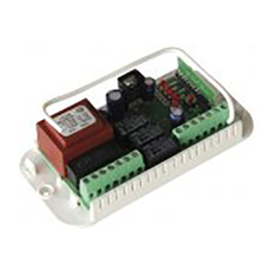
ELECTRONIC PANEL LRX 2035 ALARM
Control panel that integrates electronic control for single-phase
motor 230 Vac and Alarm System for the supervision of 2 wired
zones.
The control panel, equipped with intergrated battery charger
and radio receiver, is ideal for automation and safety of garage
doors, over head doors and rolling shutters.
The control panel can be used in a combine manner, so that
the management of automation and alarm system is reported to
a single command, or so that a separate control for automation
alone and a control for the alarm system alone.
- Mod. LRS 2035 Alarm
- Mod. LRS 2035 SET Alarm
- Mod. LRH 2035 Alarm
IMPORTANT FOR THE USER
-The device can be used by up to 8-year-old children or
persons with reduced physical-psychological abilities or
with little knowledge and experience, only if they are
supervised or trained on the functioning and the use
modalities in a safe way, to better know also the dangers
during its use.
- This instructions are available also on the website
www.seav.com.
- Do not allow children to play with the device and keep
the radio-controls away from their reach.
Frequently examine the plant to detect any signs of
damaging. Do not use the device if a repair intervention is
necessary.
-Always remember toremove the power source before
polish or maintenace works.
-Polish and maintenance works must not be done by
children without any supervision.
ATTENTION: keep this instruction manual and respect
the important safety prescriptions contained herein.
The not compliance with the prescriptions may cause
damages and serious accidents.
IMPORTANT FOR THE INSTALLER
1)Before automating the frame, check that it is in good
conditions, in compliance with the Machinery Directive
and with EN 12604.
2) Control that place, where the installation is situated,
respects the Temperature working limits, fixed for the
device.
3) The safety for the final installation and the respect of all
the rules (EN 12453 – EN 12445) are under responsability
of the person, who Assembly all the parts together for
building a closing.
4) Use safety disposals which can control their connection
to the Electric panel.
5)To be sure of having done a right installation, you
should do a coplete check-up (progra-mation of the
electric unit and correct installation of safety disposals).
6) In the back side, the shell is equipped with wall
fastening set up (holes for fastening by dowels or screws).
Consider and implement all Efforts for an installation that
does not change the IP degree.
: 433,92 Mhz
: 433,92 Mhz "narrow band"
: 868,3 Mhz "narrow band"
GB
7) The control unit does not have any type of isolating
device
for the 230 Vac line. It will therefore be the
responsibility of the installer to Arrange an isolating device
inside the plant. It is necessary to install A monophase
switch with over-voltage category III. It must be Positioned
where it can protected from accidental closing, according
To that prescribed in point 5.2.9. of EN 12453.
8) For what concerning cables for power, you should use
flexible Cables under policloroprene insulating sheath of
harmonized type (H05RN-F) with 1mm² minimum size of
conductor wires.
9) The gearmotor used to move the frame must comply
with that prescribed at point 5.2.7 of EN 12453.
10) In compliance with 5.4.2 of EN 12453, it is
recommended to use gearmotors equipped with an
electric-mechanical release device, so that the door can
be moved manually in case of necessity.
11) In compliance with 5.4.3 of EN 12453, use electric-
mechanical release systems or similar devices which stop
the door safely in the end run position.
12) Wiring of the various electrical components outside of
the control unit must be carried out in compliance with that
prescribed in Standard EN 60204-1 and its amendments
at point 5.2.7 of EN 12453. Cables for power can have a
14 mm Maximum diameter size.
connection cables must be fixed using the cable "optional"
provided. Please Be aware of fixing the cables in order to
attach them in a solid Way. Moreover, during the shell
drilling phase to let the power and connection cables go
through, and the cable glands assembly, warning to Install
everything in order to maintain unchanged the IP-degree
properties of the box.
13) Mounting of a push button panel for manual control
must be done positioning the push button panel where the
user is not in a dangerous position.
14) The plastic box is lacking in anti-intrusion Tampere
connection In the removable part of the Switch, so it is
recommended the Assembly by the installer for a major
safety to the Alarm system.
15) The safety function, guaranteed by the electronic unit,
operates Only during the closure; so the opening
protection must be Guaranteed by independent actions
(havens or safety distance) From the control circuit during
the installation.
16) For a correct functioning of the radio receiver, if using
one or More control units, the installation at a minimum
distance of at least 3 metres one from the other is
recommended.
Electronic control unit:
LRS 2035 SET Alarm – LRH 2035 Alarm
Comply with the specifications of the Directives
R&TTE 99/5/EC, EMC 2004/108/EC, LVD 2006/95/EC.
Power supply and
LRS 2035 Alarm
Advertisement

Summary of Contents for R&TTE LRX 2035
- Page 1 ELECTRONIC PANEL LRX 2035 ALARM 7) The control unit does not have any type of isolating device for the 230 Vac line. It will therefore be the Control panel that integrates electronic control for single-phase responsibility of the installer to Arrange an isolating device motor 230 Vac and Alarm System for the supervision of 2 wired inside the plant.
-
Page 2: Technical Data
TECHNICAL DATA: Automatic closing: - Power supply: 230 Vac 50-60Hz 900W (4A) max. The control unit closes the frame automatically without sending - Flashing light output: 230 Vac 50-60 Hz other Commands. The choice of this operating mode is 100W Resistive Load max. described under The instruction for setting the delay period. - Page 3 Buffer Battery 12V 2,7Ah max: 2) CODE ALARM: (Programming of the radio control for the It is possible to connect a buffer battery to make in work only Activation/deactivation of the alarm system ). the Alarm system, also with electrical line missing. Moreover it The method of programming and cancellation is similar to the has An incorporated battery charger 13,8V (both for buffer one Described before, but related to LED CODE ALARM, with...
-
Page 4: Extended Menu
the LED LAMP/CORT will switch on permanently And the programming is done. Repeat the operation if wanting to restore the previous configuration. EXTENDED MENU’ 1 D) T. MOT. (Lamp light function): The control unit is supplied by the manufacturer with the option The control unit is supplied with permanently flashing lamp of selecting only the functions listed in the main menu. - Page 5 present while closing function disabled. If you wish to enable the function, proceed as follows: check that the extended menu 2 is enabled (flagging by 1110-1110-1110.. flashing T. PAUSE LEDs start flashing simultaneously), use the SEL button to navigate to the LAMP/CORT LED when flashing and press the SET button: the LAMP/CORT LED remains lit in a constant manner and programming is complete.
- Page 6 Rev. 1.2 date 21-04-2015...
Need help?
Do you have a question about the LRX 2035 and is the answer not in the manual?
Questions and answers